

How to Get Started with L298N Motor Driver module using Arduino
The L298N motor driver module is a cheap solution when you need to drive a 2 DC motors or 1 stepper motor. It is a popular motor driver module to the DIYers and hobbyist due to ease of use and availability.
Features:
It has a dual H-bridge motor driver.
Onboard 5V linear voltage regulator so it means you can supply the voltage requirements of the other circuit.
Below is the pin assignments and its configuration.
Power Terminal Block:
+12V:
- is the positive motor supply voltage
- if motor supply voltage is more than 12V, make sure the jumper pin in CON5 is removed. This is to protect the onboard 5V linear voltage regulator from damage.
GND:
- is the common ground for the L298N and the interface microcontroller
+5V:
- it is an input voltage supply for the L298N IC when the onboard 5V linear voltage regulator is disabled (jumper pin in CON5 is removed).
- it is an output voltage supply for the interface microcontroller when the linear voltage regulator is enabled (jumper pin in CON5 is in placed).
Bidirectional Motor Driver Output:
MotorA: motor driver output for MotorA
MotorB: motor driver output for MotorB
Enable and Speed Controller:
enA: enable pin A
- Pull down (connect to GND) to disable motor driver output for MotorA
- Pull up (connect to VCC) to enable motor driver output for MotorB (similar results is achieve using jumper pin)
- PWM to control speed of the motor
enB: enable pin B
- Pull down (connect to GND) to disable motor driver output for MotorA
- Pull up (connect to VCC) to enable motor driver output for MotorB (similar results is achieve using jumper pin)
- PWM to control speed of the motor
Direction Logic Controller:
IN1 and IN2:
- direction logic controller for MotorA
IN3 and IN4:
- direction logic controller for MotorB
PWR jumper pin:
- this is to enable onboard voltage regulator
Circuit Diagram:
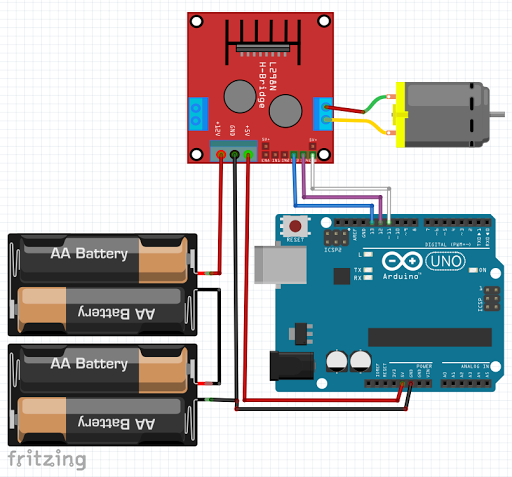
NOTES:
- Referring to the circuit diagram, I am supplying the L298N with 6V battery. +6V is connected to the +12V pin motor supply voltage.
- Battery GND pin is connected to the GND pin of the L298N.
- Arduino GND is also tied to the L298N GND pin, this is to create a common reference ground.
- 5V pin of Arduino is tied to the L298N +5V pin to supply voltage for the L298N IC. Please notice also that the jumper pin in the CON5 is removed to disable the onboard 5V voltage regulator of the L298N.
- DC motor is connected to the terminal block MotorB in the right side.
- IN3 and IN4 is tied to Arduino Uno digital pin 13 and 12 to control the direction of motor rotation.
- EnB is tied to Arduino Uno digital pin 11. This pin has a capability of outputting a Pulse Width Modulation (PWM) signal. This is to control the speed of rotation of the motor.
Video Demonstration:
Source Code:
#define IN3B 13
#define IN4B 12
#define PWMB 11


String cmd="";
bool isBEnabled = false;
byte PWMB_val = 100;

void setup() {
  // put your setup code here, to run once:
  Serial.begin(9600);

  pinMode(IN3B, OUTPUT);
  pinMode(IN4B, OUTPUT);
  pinMode(PWMB, OUTPUT);

  digitalWrite(IN3B, LOW);
  digitalWrite(IN4B, LOW);
  digitalWrite(PWMB, LOW);
}

void loop() {
  // put your main code here, to run repeatedly:
  checkSerial();
}


void checkSerial() {
 //Read data from Serial
 while(Serial.available()>0){
   cmd+=(char)Serial.read();
 }

 //Select function with cmd
 if(cmd!=""){
    cmd.trim();  // Remove added LF in transmit
    // We expect Command from bluetooth
    if (cmd.equals("E")) {
      Serial.println("Enabling motor");
      enableB();
    } else if(cmd.equals("R")) {
       Serial.println("CW Rotation");
       forward();
    }else if (cmd.equals("L")){
       Serial.println("CCW Rotation");
       backward();
    }else if(cmd.equals("U")){
       Serial.println("Speed up");
       speedUp();
    }else if(cmd.equals("D")){
       Serial.println("Speed down");
       speedDown();
    }
    cmd=""; //reset cmd
  }

void enableB() {
  if (isBEnabled) {
    // motor is running, now disable it
    isBEnabled = false;
    digitalWrite(PWMB, 0);
  } else {
    // motor is disabled, now run it
    isBEnabled = true;
    analogWrite(PWMB, PWMB_val);
  }
}

void forward() {
  digitalWrite(IN3B, LOW);
  digitalWrite(IN4B, HIGH);
}

void backward() {
  digitalWrite(IN3B, HIGH);
  digitalWrite(IN4B, LOW);
}

void speedUp() {
  if (PWMB_val < 245) {
    PWMB_val = PWMB_val + 10;
    analogWrite(PWMB, PWMB_val);
  }
}

void speedDown () {
  if (PWMB_val > 9) {
    PWMB_val = PWMB_val - 10;
    analogWrite(PWMB, PWMB_val);
  }
}
That’s all for now. If you have any questions or clarification, please feel free to leave your comments and suggestions in the comment box.
Thank you and have a good day.
Happy tinkering.