

Tutorial: Getting Started with the NRF24L01 | How to use | Arduino
NRF24L01 is one of the cheapest wireless radio module available in the market. In here you will learn how to interface it to Arduino and use it for controlling something remotely.
Pin Assignment:

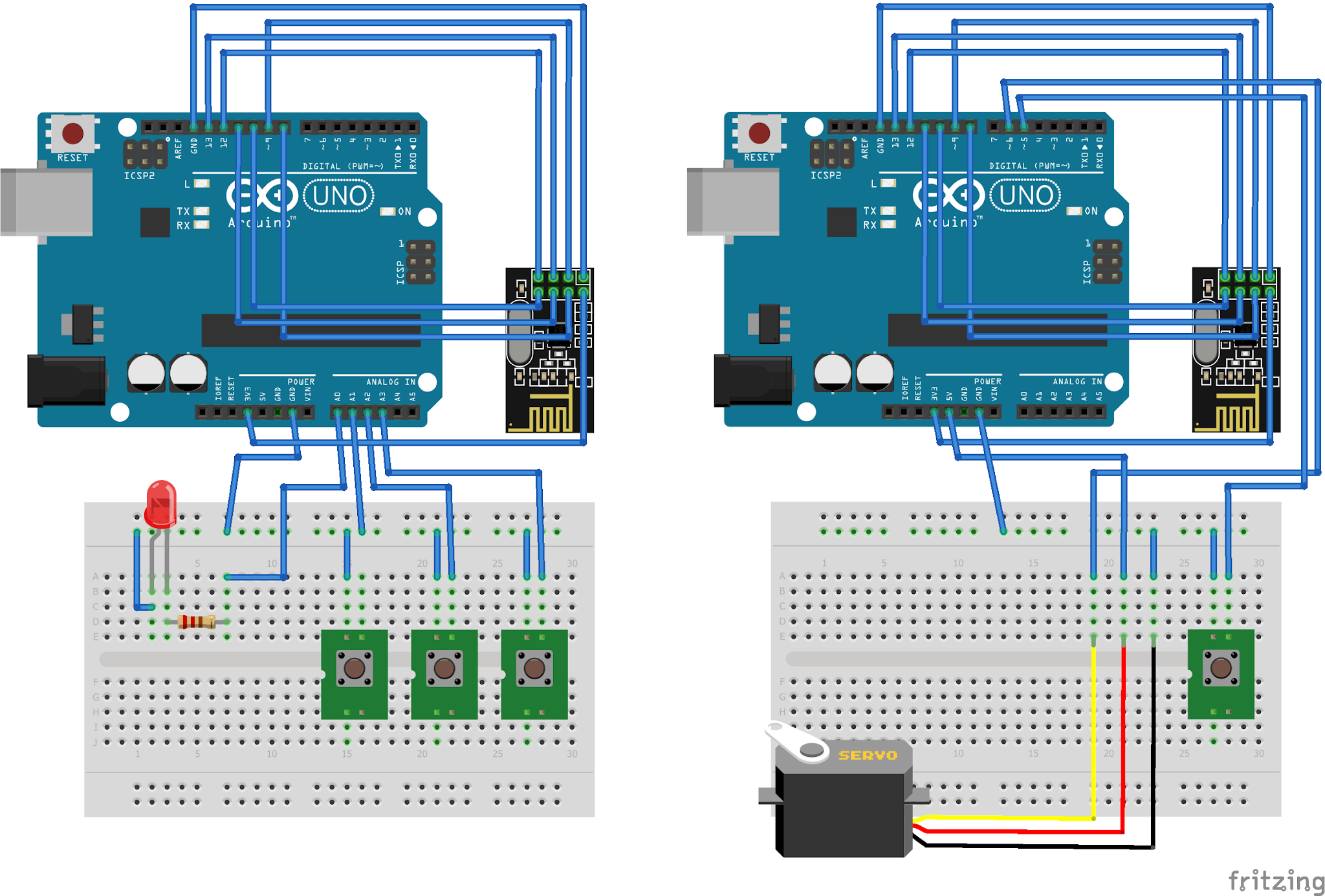
Circuit Diagram:
Instruction:
1. Connect the NRF GND pin 1 to Arduino Uno GND pin
2. Connect the NRF VCC pin 2 to Arduino Uno 3.3V pin
3. Connect the NRF CE pin 3 to Arduino Uno digital pin 9
4. Connect the NRF CSN pin 4 to Arduino Uno digital pin 8
5. Connect the NRF SCK pin 5 to Arduino Uno digital pin 13
6. Connect the NRF MOSI pin 6 to Arduino Uno digital pin 11
7. Connect the NRF MISO pin 7 to Arduino Uno digital pin 12
8. Connect the NRF IRQ pin 8 to Arduino Uno digital pin 10, we will not use
For node A:
9. Connect an LED with limiting resistor to Arduino Uno analog pin A0
10. Connect 3pcs of tactile switch buttons to Arduino Uno analog pins A1, A2, and A3. The other pins of the switch should be connected to the ground for an active LOW logic. Internal pullup will be use.
For node B:
11. Connect the signal pin of the servo motor to the Arduino Uno digital pin 6 PWM output. Servo motor VCC and GND pin will be connected to Arduino Uno 5V pin and GND. This is ok to do if you have a small servo but you may also use external power supply for the servo.
12. Connect a tactile switch button to Arduino Uno digital pin 5. The other pins of the switch should be connected to the ground for an active LOW logic. Internal pullup will be use.
Video Demonstration:
If you found this tutorial as helpful, please give me thumbs up and Share this to your friends.
And if you have any question regarding this tutorial, please write it in the comment box.
Thank you and have a good day.
Source Code:
Node A sketch:
#include "SPI.h"    // Library for SPI communication protocol
#include "RF24.h"   // Library for the NRF24L01 module

#define led A0      // pin assignments for the LED
#define SW1 A1      // pin assignments for the tactile switches
#define SW2 A2
#define SW3 A3
RF24 radio(9, 8);   // pin assignments for the NRF CE, CSN

// Node addresses
const byte addresses[][6] = {"00001", "00002"};
boolean buttonState = 0;
int angle = 0;

void setup() {
  pinMode(led, OUTPUT);
  pinMode(SW1, INPUT_PULLUP);
  pinMode(SW2, INPUT_PULLUP);
  pinMode(SW3, INPUT_PULLUP);

  radio.begin();
  radio.openWritingPipe(addresses[1]);    // 00002
  radio.openReadingPipe(4, addresses[0]); // 00001
  radio.setPALevel(RF24_PA_MIN);
}
void loop() {
  // Transmit to node B:
  //    In here we will transmit the angle for the
  //      servo motor attached in the other node
  delay(10);
  radio.stopListening();
  if        (digitalRead(SW1) == LOW) {
    angle = 60;
  } else if (digitalRead(SW2) == LOW) {
    angle = 120;
  } else if (digitalRead(SW3) == LOW) {
    angle = 180;
  } else {
    angle = 0;
  }
  radio.write(&angle, sizeof(angle));
  // Receive from node B:
  //    In here we will receive the button state
  //      from the other node and if the button is press,
  //      lights the LED on
  delay(10);
  radio.startListening();
  while (!radio.available());
  radio.read(&buttonState, sizeof(buttonState));
  digitalWrite(led, !buttonState);
}
Node B sketch:
#include "SPI.h"      // Library for SPI communication protocol
#include "RF24.h"     // Library for the NRF24L01 module
#include "Servo.h"    // Library for the servo motor

#define button 5      // pin assignments for the tactile switch
#define servo  6      // pin assignments for the servo motor
RF24 radio(9, 8);     // pin assignments for the NRF CE, CSN
Servo myServo;        // instantiate the servo motor as myServo

// Node addresses
const byte addresses[][6] = {"00001", "00002"};
boolean buttonState = 0;

void setup() {
  pinMode(button, INPUT_PULLUP);
  myServo.attach(servo);

  radio.begin();
  radio.openWritingPipe(addresses[0]);    // 00001
  radio.openReadingPipe(4, addresses[1]); // 00002
  radio.setPALevel(RF24_PA_MIN);
}
void loop() {
  // Receive from node A:
  //    In here we will receive the angle sent from the other node
  //      and consequently write it in the servo connected
  delay(10);
  radio.startListening();
  if ( radio.available()) {
    while (radio.available()) {
      int angleV = 0;
      radio.read(&angleV, sizeof(angleV));
      myServo.write(angleV);
    }
  }
  // Transmit to node A:
  //    In here we will transmit the button state to the other
  //      node.
  delay(10);
  radio.stopListening();
  buttonState = digitalRead(button);
  radio.write(&buttonState, sizeof(buttonState));
}