

017 – MicroPython TechNotes: LASER Module
In this article, we will learn on how to use a LASER module with ESP32 using MicroPython programming language.
PINOUT:
- G – for the ground pin.
- V – for the supply voltage.
- S – for the control signal pin.
BILL OF MATERIALS:
- ESP32 development board with MicroPython firmware that will serve as the main microcontroller.
- ESP32 shield from Gorillacell ESP32 development kit to extend the pins of ESP32 and to provide easy circuit connection.
- 3-pin female-female dupont jumper wires.
- And of course the LASER module itself.
HARDWARE INSTRUCTION:
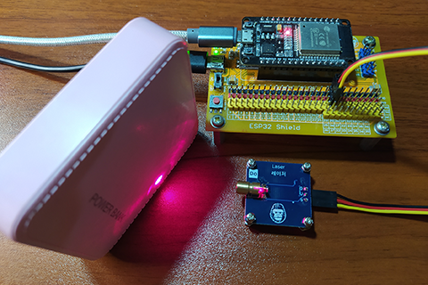
- First, attach the ESP32 development board on top of the ESP32 shield and make sure that both USB port are on the same side.
- Next, attach the dupont wires to the LASER module by following the color coding which black for the ground, red for the VCC, and yellow for the control signal pin.
- Next, attach the other side of the dupont jumper wires to the ESP32 shield by matching the colors of the wires to the colors of the pin headers which is black to black, red to red, and yellow to yellow. For this experiment, I choose GPIO 25 because this ESP32 shield provides 5V on GPIO 25.
- Next, power the ESP32 shield with an external power supply with type-C USB connector. Make sure that the power switch is set to ON state.
- Next, connect the ESP32 to the computer through a micro-USB cable. The demo circuit should be ready.
SOFTWARE INSTRUCTION:
For this experiment, I prepared 2 example source code. Just copy and paste it in Thonny. Enjoy.
VIDEO DEMONSTRATION:
CALL TO ACTION:
For any concern, write your message in the comment section.
You might also like to support my journey on Youtube by Subscribing. Click this to Subscribe to TechToTinker.
Thank you and have a good days ahead.
See you,
– George Bantique | tech.to.tinker@gmail.com
SOURCE CODE:
1. Example # 1, basic and simple control of LASER module:
# More details can be found in TechToTinker.blogspot.com
# George Bantique | tech.to.tinker@gmail.com

from machine import Pin

laser = Pin(25, Pin.OUT)

# # The following source should be tested using the REPL:
# laser.on()  # Turns ON the laser.
# laser.off() # Turns OFF the laser.
How the code works:
from machine import Pin
Loads or imports the necessary library, in this case the Pin class from the machine module. This is in order to access the pins of ESP32.
laser = Pin(25, Pin.OUT)
This line of code creates the object named laser which is connected on GPIO 25 with a pin direction set as an output.
laser.on()
This will set the pin to logic HIGH which will turn ON the laser module.
laser.off()
This will clear the pin to logic LOW which will turn OFF the laser module.
2. Example # 2, SOS using the LASER module:
# More details can be found in TechToTinker.blogspot.com
# George Bantique | tech.to.tinker@gmail.com

from machine import Pin
from time import ticks_ms

laser = Pin(25, Pin.OUT)
switch = Pin(0, Pin.IN, Pin.PULL_UP)

DOTS_INTERVAL = 250
DASH_INTERVAL = 750
LOWS_INTERVAL = 500
BETW_INTERVAL = 700

isSOS = False
startTime = ticks_ms()
steps = 0

while True:
    if isSOS:
        if steps == 1 or steps == 3 or steps == 5:
            laser.on()
            if ticks_ms() - startTime >= DOTS_INTERVAL :
                steps += 1
                startTime = ticks_ms()
        elif steps == 7 or steps == 9 or steps == 11:
            laser.on()
            if ticks_ms() - startTime >= DASH_INTERVAL:
                steps += 1
                startTime = ticks_ms()
        elif steps == 0 or steps == 6 or steps == 12:
            laser.off()
            if ticks_ms() - startTime >= BETW_INTERVAL:
                steps += 1
                startTime = ticks_ms()
        else:
            laser.off()
            if ticks_ms() - startTime >= LOWS_INTERVAL:
                steps += 1
                startTime = ticks_ms()

        if steps > 12:
             steps = 0

    if switch.value() == 0:
        laser.off()
        #print('press')
        isSOS = not isSOS
        steps = 0
        sleep_ms(300)
How the code works:
from machine import Pin
from time import ticks_ms
Loads the necessary libraries needed. ticks_ms class from time module will return a time value in milliseconds that ticks every 1 milliseconds, hence its name.
laser = Pin(25, Pin.OUT)
switch = Pin(2, Pin.IN, Pin.PULL_UP)
Creates the objects for the laser and the switch.
The switch object is connected to GPIO 2 with pin direction set as input and the internal pull-up resistor is enabled. The pull-up resistor will prevent tri-state or unknown state (it will make sure that the pin can be read with a known digital value, either 1 or 0). An input pin with pull-up resistor will have default value of (logic) 1 when the button is not press else the value is (logic) 0.
DOTS_INTERVAL = 250
DASH_INTERVAL = 750
LOWS_INTERVAL = 500
BETW_INTERVAL = 700
This are constants that will be use as an individual interval for the SOS signal
isSOS = False
startTime = ticks_ms()
steps = 0
This are variables:
isSOS flag will determine if the sending of SOS signal should be started.
startTime captures the beginning of the timer counter.
steps variable holds the current steps in SOS signal.
while True:
Creates the infinite loop for the program.
if isSOS:
if steps == 1 or steps == 3 or steps == 5:
laser.on()
if ticks_ms() – startTime >= DOTS_INTERVAL :
steps += 1
startTime = ticks_ms()
elif steps == 7 or steps == 9 or steps == 11:
laser.on()
if ticks_ms() – startTime >= DASH_INTERVAL:
steps += 1
startTime = ticks_ms()
elif steps == 0 or steps == 6 or steps == 12:
laser.off()
if ticks_ms() – startTime >= BETW_INTERVAL:
steps += 1
startTime = ticks_ms()
else:
laser.off()
if ticks_ms() – startTime >= LOWS_INTERVAL:
steps += 1
startTime = ticks_ms()
This lines of code creates the SOS signal.
if steps > 12:
steps = 0
This makes sure that SOS signal repeats itself.
if switch.value() == 0:
laser.off()
#print(‘press’)
isSOS = not isSOS
steps = 0
sleep_ms(300)
This if statement reads the current state of the pin associated to switch object which is connected on GPIO 2. If the read value is 0, it means that the switch is press.
If the switch is press, turns OFF the laser module, toggled the isSOS flag, reset the steps variable to 0, and a delay of 300 milliseconds to prevent multiple detection of switch press.
REFERENCES AND CREDITS:
Purchased your Gorillacell ESP32 development kit at: