

021 – MicroPython TechNotes: Color Touch Sensor
In this article, we will learn how to use a color touch sensor module with ESP32 using MicroPython programming language.
PINOUT:
- G – for the ground.
- V – for the supply voltage.
- S – for the signal pin.
BILL OF MATERIALS:
- An ESP32 development board that will serve as the brain for this experiment.
- An ESP32 shield from Gorillacell ESP32 development kit to extend the pins to pin headers for easy circuit connection.
- A 3-pin female-female dupont jumper wires to attach the color touch sensor module to the ESP32 shield pin headers.
- And of course the color touch sensor modules itself.
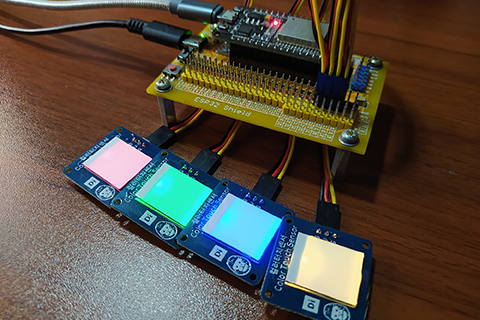
HARDWARE INSTRUCTION:
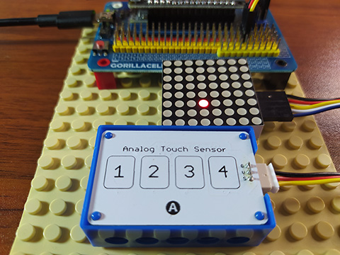
- First, attach the ESP32 board on top of the ESP32 shield and make sure that both USB port are on the same side.
- Next, attach the dupont wires to the color touch sensor by following the color coding which is black for the ground, red for the VCC, and yellow for the signal pin.
- Next, attach the other end of the dupont wires to the ESP32 shield by matching the colors of the wires to the colors of the pin headers which is black to black, red to red, and yellow to yellow. For this experiment I choose GPIO 32, GPIO 33, GPIO 34, and GPIO 35 for the red, green, blue, and rainbow color touch sensor respectively.
- Next, power the ESP32 shield with an external power supply with a type-C USB connector and make sure that the power switch is set to ON state.
- Lastly, connect the ESP32 to the computer through the micro USB cable. Our demo circuit should now be ready.
SOFTWARE INSTRUCTION:
I prepared 5 examples below which you can copy and paste to your Thonny IDE.
Play with it and modify it to adapt according to your needs.
Hope you enjoy it by learning. Happy tinkering!
VIDEO DEMONSTRATION:
For any concern, write your message in the comment section.
You might also like to support my journey on Youtube by Subscribing. Click this to Subscribe to TechToTinker.
Thank you and have a good days ahead.
See you,
– George Bantique | tech.to.tinker@gmail.com
SOURCE CODE:
1. Example # 1, exploring the basics:
# More details can be found in TechToTinker.blogspot.com
# George Bantique | tech.to.tinker@gmail.com

from machine import Pin

cts = Pin(32, Pin.IN)

# # The following lines of code can be tested in the REPL:
# cts.value() # Reads the current value of the color touch sensor.
# # Return value is 1 when color touch sensor is touch,
# # the value is 0 when color touch sensor is not being touch.
How the code works:
from machine import Pin
Imports the Pin class from machine module in order to access ESP32 pins.
cts = Pin(32, Pin.IN)
Creates a Pin object named cts (short for color touch sensor) which is connected on GPIO 32 with pin direction set as input.
cts.value()
Reads the digital value of the pin associated to cts object, in our case GPIO 32. Returned value is either 1 when the touch sensor is currently press else returned value is 0.
2. Example # 2, multiple color touch sensor:
# More details can be found in TechToTinker.blogspot.com
# George Bantique | tech.to.tinker@gmail.com

from machine import Pin
from time import sleep_ms

red_cts = Pin(32, Pin.IN)
grn_cts = Pin(33, Pin.IN)
blu_cts = Pin(34, Pin.IN)
rbw_cts = Pin(35, Pin.IN)
isRed = red_cts.value()
isGrn = grn_cts.value()
isBlu = blu_cts.value()
isRbw = rbw_cts.value()


while True:
    if red_cts.value()==1:
        if isRed==False:
            isRed = True
            print('Red color touch sensor is activated.')
    else:
        isRed = False

    if grn_cts.value()==1:
        if isGrn==False:
            isGrn = True
            print('Green color touch sensor is activated.')
    else:
        isGrn = False

    if blu_cts.value()==1:
        if isBlu==False:
            isBlu = True
            print('Blue color touch sensor is activated.')
    else:
        isBlu = False

    if rbw_cts.value()==1:
        if isRbw==False:
            isRbw = True
            print('Rainbow color touch sensor is activated.')
    else:
        isRbw = False

    sleep_ms(300)
How the code works:
from machine import Pin
Loads the Pin class from machine module in order to access ESP32 pins.
from time import sleep_ms
Imports sleep_ms class from time module for creating a time delay with milliseconds resolution.
red_cts = Pin(32, Pin.IN)
grn_cts = Pin(33, Pin.IN)
blu_cts = Pin(34, Pin.IN)
rbw_cts = Pin(35, Pin.IN)
Creates the Pin objects for all the available color touch sensor which are connected to GPIO 32, 33, 34, and 35 respectively.
isRed = red_cts.value()
isGrn = grn_cts.value()
isBlu = blu_cts.value()
isRbw = rbw_cts.value()
Creates a variable flags for each color touch sensor and initialized it by reading the digital state of the associated pin.
while True:
Creates an infinite to constantly checks for the color touch sensor state.
if red_cts.value()==1:
if isRed==False:
isRed = True
print(‘Red color touch sensor is activated.’)
else:
isRed = False
Checks if the specific color touch sensor is currently active. If yes, check if it is previously inactive. This works similar to “rising edge” detection. If both condition is satisfied, set the variable flag to True then send a print message in REPL. Else (if the color touch sensor is inactive), then set the variable flag to False. This applies to all other color touch sensor.
sleep_ms(300)
Creates a 300 milliseconds interval.
3. Example # 3, introducing pin interrupt:
# More details can be found in TechToTinker.blogspot.com
# George Bantique | tech.to.tinker@gmail.com

from machine import Pin

red_cts = Pin(32, Pin.IN)
led = Pin(2, Pin.OUT)

def handle_interrupt(pin):
    led.value(not led.value())
    print('LED is toggled.')

# Use Pin.IRQ_RISING to set interrupt trigger to rising edge.
# Use Pin.IRQ_FALLING to set interrupt trigger to falling edge.
# Use Pin.IRQ_RISING | Pin.IRQ_FALLING to set interrupt trigger to both edge.
# Interrupt with rising edge detects signal change from logic LOW to logic HIGH.
# Interrupt with falling edge detects signal change from logic HIGH to logic LOW.
red_cts.irq(trigger=Pin.IRQ_RISING, handler=handle_interrupt)
How the code works:
from machine import Pin
Loads the Pin class from machine module in order to access the ESP32 GPIO pins.
red_cts = Pin(32, Pin.IN)
Creates a Pin object named red_cts which is connected to GPIO 32 with pin direction set as an input.
led = Pin(2, Pin.OUT)
Creates a Pin object named led which is the onboard LED on GPIO 2 with pin direction set as output.
def handle_interrupt(pin):
led.value(not led.value())
print(‘LED is toggled.’)
Creates a function that will be called when the interrupt is triggered. This will trigger the state of the led pin and send a message in the REPL.
red_cts.irq(trigger=Pin.IRQ_RISING, handler=handle_interrupt)
Attaches the red_cts pin to interrupt using the “.irq” method.
trigger parameter sets the what edge detection to be use. It can be either rising-edge detection or falling-edge detection or both using the logic OR.
handler parameter sets what callback function to be called when the interrupt occurs.
4. Example # 4, multiple pin interrupt:
# More details can be found in TechToTinker.blogspot.com
# George Bantique | tech.to.tinker@gmail.com

from machine import Pin

red_cts = Pin(32, Pin.IN)
grn_cts = Pin(33, Pin.IN)
blu_cts = Pin(34, Pin.IN)
rbw_cts = Pin(35, Pin.IN)

def handle_interrupt(pin):
    print(pin)

# Use Pin.IRQ_RISING to set interrupt trigger to rising edge.
# Use Pin.IRQ_FALLING to set interrupt trigger to falling edge.
# Use Pin.IRQ_RISING | Pin.IRQ_FALLING to set interrupt trigger to both edge.
# Interrupt with rising edge detects signal change from logic LOW to logic HIGH.
# Interrupt with falling edge detects signal change from logic HIGH to logic LOW.
red_cts.irq(trigger=Pin.IRQ_RISING | Pin.IRQ_FALLING, handler=handle_interrupt)
grn_cts.irq(trigger=Pin.IRQ_RISING | Pin.IRQ_FALLING, handler=handle_interrupt)
blu_cts.irq(trigger=Pin.IRQ_RISING | Pin.IRQ_FALLING, handler=handle_interrupt)
rbw_cts.irq(trigger=Pin.IRQ_RISING | Pin.IRQ_FALLING, handler=handle_interrupt)
This just shows how to use multiple pin interrupts by expanding the Example # 3.
5. Example # 5, simple pin interrupt example:
# More details can be found in TechToTinker.blogspot.com
# George Bantique | tech.to.tinker@gmail.com

from machine import Pin
from time import sleep_ms

red_cts = Pin(32, Pin.IN)
grn_cts = Pin(33, Pin.IN)
blu_cts = Pin(34, Pin.IN)
rbw_cts = Pin(35, Pin.IN)
led = Pin(2, Pin.OUT)

press = False
irq_pin = 0

def handle_interrupt(pin):
    global press
    press = True
    global irq_pin
    irq_pin = int(str(pin)[4:-1])
"""
   String slicing [<start position>,<end position>]
   positive value - starts counting from left-hand side
   negative value - starts counting from right-hand side
   For example:
     If you press red color touch sensor it will return:
       Pin(32)
     Now to get only the integer value, we can slice the string
     by removing the "Pin(" and that is 4 position from left.
     We also need to remove the ")" and that is 1 position from right
     (use negative "-" to indicate slice from right).
     Which leaves a string "32".
     And to make it as an integer value, we can use an int() casting.
   """

red_cts.irq(trigger=Pin.IRQ_RISING, handler=handle_interrupt)
grn_cts.irq(trigger=Pin.IRQ_RISING, handler=handle_interrupt)
blu_cts.irq(trigger=Pin.IRQ_RISING, handler=handle_interrupt)
rbw_cts.irq(trigger=Pin.IRQ_RISING, handler=handle_interrupt)

while True:
    if press:
        press = False
        if irq_pin == 32:
            print('Red color touch sensor triggered.')
        if irq_pin == 33:
            print('Green color touch sensor triggered.')
        if irq_pin == 34:
            print('Blue color touch sensor triggered.')
        if irq_pin == 35:
            print('Rainbow color touch sensor triggered.')
This code works still the same as Example # 3 and Example # 4.
REFERENCES AND CREDITS:
REFERENCES and CREDITS:
Purchase your Gorillacell ESP32 development kit at: