

013 – MicroPython TechNotes: 8×16 Dot Matrix Display (SPI)
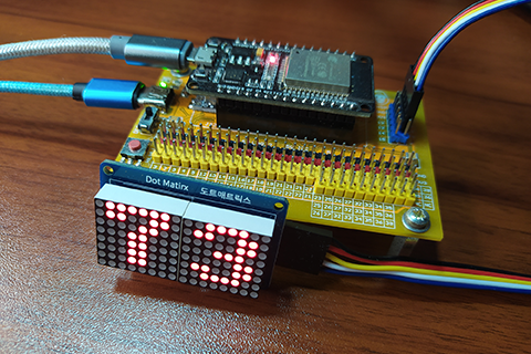
In this article, we will look at the 8×16 Dot Matrix Display with SPI as communication interface. This is basically the continuation of the previous tutorial on how to use the 8×8 Matrix Display.
BILL OF MATERIALS:
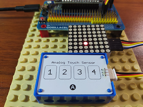
- ESP32 development board.
- Gorillacell ESP32 shield.
- 5-pin female-female dupont jumper wires.
- 8×16 Dot Matrix display – SPI interface.
PINOUT:
- GND – for the ground.
- VCC – for the supply voltage.
- DIN – for the SPI data input pin.
- CLK – for the SPI clock pin.
- CS – for the SPI chip select pin.
HARDWARE INSTRUCTION:
- Attach ESP32 dev board on top of ESP32 shield and make sure that both USB port is on the same side.
- Attach the dupont wires to the 8×16 dot matrix display according to the color coding which is black for the ground, red for the VCC, yellow for the DIN pin, white for the CLK pin, and blue for the CS pin.
- Attach the other side of the dupont jumper wires to the pin headers of ESP32 shield by matching its colors that is black to black, red to red, yellow and the following colors to yellow pin headers.
- Power the ESP32 shield by connecting an external power supply with a type-C USB connector and make sure that the power switch is slide to ON state.
- Connect the ESP32 to the computer through the micro USB cable. The demo circuit should now be ready.
SOFTWARE INSTRUCTION:
- Save the max7219.py driver library below from the SOURCE CODE section of this blog post to the ESP32 MicroPython device root directory.
- Enjoy learning by trying the example source codes.
- Further the learning process by modifying it according to your liking.
VIDEO DEMONSTRATION:
CALL TO ACTION:
For any concern, write your message in the comment section.
You might also like to support my journey on Youtube by Subscribing. Click this to Subscribe to TechToTinker.
Thank you and have a good days ahead.
See you,
– George Bantique | tech.to.tinker@gmail.com
SOURCE CODE:
1. Example # 1, exploring the basics:
from machine import Pin, SPI
from max7219 import Max7219

spi = SPI(1,
          baudrate=10000000,
          polarity=1,
          phase=0,
          sck=Pin(19),
          mosi=Pin(23))
cs = Pin(18, Pin.OUT)
display = Max7219(16, 8, spi, cs, False)


# The following codes should be tested using the REPL:
# 1. To display a character:
display.text('A',0,0)
display.show()
# 2. To clear the display:
# display.fill(0)
# 3. To modify the default brightness:
# display.brightness(0)  # minimum brightness
display.brightness(15) # maximum brightness
# 4. To display a scrolling message:
# display.marquee('Hello world')
# ****************************************************
# Other graphic primitives:
# 5. To display a single pixel:
# display.pixel(x, y[, c])
# 6. To display a horizontal line:
# display.hline(x, y, w, col)
# 7. To display a vertical line:
# display.vline(x, y, h, col)
# 8. To display a line:
# display.line(x1, y1, x2, y2, col)
# 9. To display a rectangle:
# display.rect(x, y, w, h, col)
# 10. To display a filled rectangle:
# display.fill_rect(x, y, w, h, col)
# 11. To scroll the display:
# display.scroll(dx, dy)
# 12. To display custom character:
# display.blit(fbuf, x, y[, key])
2. Example # 2, binary clock:
from machine import Pin, SPI
 from max7219 import Max7219
 from time import sleep_ms
 spi = SPI(1,
      baudrate=10000000,
      polarity=1,
      phase=0,
      sck=Pin(19),
      mosi=Pin(23))
 cs = Pin(18, Pin.OUT)
 display = Max7219(16, 8, spi, cs, False)
 counter = 0
 isCountUp = True
 while True:
   # count up
   if isCountUp:
     if counter < 99:
       counter += 1
       if counter == 99:
         isCountUp = False
   # count down
   else:
     if counter > 0:
       counter -= 1
       if counter == 0:
         isCountUp = True
   display.fill(0)
   display.text(str(counter),0,0)
   display.show()
   sleep_ms(500)
3. max7219.py Dot Matrix Display driver library:
from machine import Pin, SPI, RTC
from max7219 import Max7219
from time import sleep

spi = SPI(1,
          baudrate=10000000,
          polarity=1,
          phase=0,
          sck=Pin(19),
          mosi=Pin(23))
cs = Pin(18, Pin.OUT)
display = Max7219(8, 8, spi, cs, True)

rtc = RTC()
rtc.datetime((2021, 2, 14, 7, 18, 11, 0, 0))
# rtc.datetime((YYYY, MM, DD, WD, HH, MM, SS, MS))
# WD 1 = Monday
# WD 7 = Sunday

def display_binary(decimal, column):
    # converts decimal number into 8-bit binary
    binary_str = '{0:8b}'.format(decimal)
    #print(binary_str)
    for row in range(0, 8):
        if binary_str[row] == '1':
            display.pixel(column, row, 1)
        else:
            display.pixel(column, row, 0)

while True:
    t = rtc.datetime()
    #display_binary(decimal value, dot matrix column)
    display_binary(t[0] % 100, 0)    # year
    display_binary(t[1], 1)          # month
    display_binary(t[2], 2)          # day
    display_binary(t[4], 4)          # hour
    display_binary(t[5], 5)          # minutes
    display_binary(t[6], 6)          # seconds
    display_binary(t[7] // 10000, 7) # subseconds
    display.show() # update the dot matrix display
    sleep(0.0001)  # 100ms wait
REFERENCES AND CREDITS:
1. Jeff Brown max7219.py: https://github.com/jgbrown32/ESP8266_MAX7219
2. Gorillacell ESP32 dev kit purchase: gorillacell.kr
I AM STUDENT OF ELECTRONICS ENGINEERING I WANT HELP FOR MY PROJECT FIRE FIGHTER ROBOT YOU REPLY ME ASAP
THANK U
Hello there. Yes of course, I would love to help anyone who wants to learn. I could guide you, but have the initiative also to learn and not just finish your school project.
By the way, what is your name?
Cheers,
George Bantique | tech.to.tinker@gmail.com