

024 – MicroPython TechNotes: Slider Switch
In this article, we will learn how to use Slider Switch with ESP32 using MicroPython programming language. A slider switch is basically a variable resistor that changes resistance according to slider wiper position. With that knowledge, we can used MicroPython’s ADC function to interpret slider switch position.
PINOUT:
- G – for the ground pin.
- V – for the supply voltage.
- S – for the signal pin.
BILL OF MATERIALS:
- ESP32 development board to serve as the brain for the experiment.
- ESP32 shield from Gorillacell ESP32 development kit to extend ESP32 pin to pin headers for easy circuit connection.
- 3-pin female-female dupont wires to connect slider switch to ESP32 shield pin headers.
- Slider Switch module from Gorillacell ESP32 development kit.
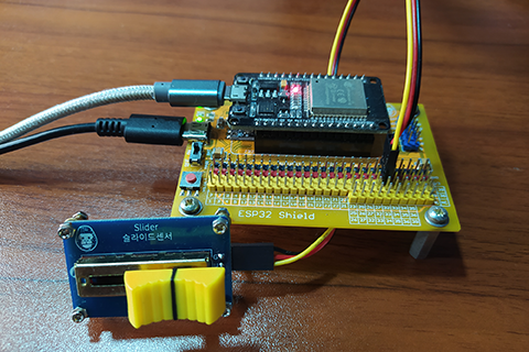
HARDWARE INSTRUCTION:
- First, attach the ESP32 on top of the ESP32 shield by making sure that the pins are properly aligned and both USB ports are on the same side.
- Next, attach the dupont wires to the Slider module by following the color coding which is black for the ground, red for the VCC, and yellow for the signal pin.
- Next, attach the other end of the dupont wires to the ESP32 shield by matching the colors of the wires to the colors of the pin headers such as black to black, red to red, and yellow to yellow. For this experiment, I choose GPIO 32 to serve as the input signal pin from the Slider module.
- Next, power the ESP32 shield with external power supply with a type-C USB connector and make sure that the power switch is set to ON state.
- Lastly, connect the ESP32 to the computer through the USB cable with micro-USB type cable. Demo circuit is now ready.
SOFTWARE INSTRUCTION:
For this experiment, I prepared to example source code for you to try.
Copy and paste it to Thonny IDE.
Please feel free to modify it and adapt according to your needs.
Happy tinkering.
VIDEO DEMONSTRATION:
For any concern, write your message in the comment section.
You might also like to support my journey on Youtube by Subscribing. Click this to Subscribe to TechToTinker.
Thank you and have a good days ahead.
See you,
– George Bantique | tech.to.tinker@gmail.com
SOURCE CODE:
1. Example # 1, basics of reading an analog input such as the slider switch:
# More details can be found in TechToTinker.blogspot.com
# George Bantique | tech.to.tinker@gmail.com

from machine import Pin, ADC
from time import sleep_ms

p32 = Pin(32, Pin.IN)
slider = ADC(p32)
slider.atten(ADC.ATTN_11DB)

while True:
    print(slider.read())
    sleep_ms(300)
How the code works:
2. Example # 2, simple application in using a slider switch:
# More details can be found in TechToTinker.blogspot.com
# George Bantique | tech.to.tinker@gmail.com

from machine import Pin, ADC, PWM
from time import sleep_ms

p32 = Pin(32, Pin.IN)
slider = ADC(p32)
slider.atten(ADC.ATTN_11DB)

boot = Pin(0, Pin.IN)
led = Pin(2, Pin.OUT)

red = PWM(Pin(25, Pin.OUT))
grn = PWM(Pin(26, Pin.OUT))
blu = PWM(Pin(27, Pin.OUT))
red.freq(60)
grn.freq(60)
blu.freq(60)

r = 0
g = 0
b = 0
steps = 0

def map(x, in_min, in_max, out_min, out_max):
    # This will not handle x value greater than in_max or
    #                      x value less than in_min
    return int((x - in_min) * (out_max - out_min) / (in_max - in_min) + out_min)

while True:
    if steps==0:
        # Set the RGB from r, g, b values
        red.duty(r)
        grn.duty(g)
        blu.duty(b)
        if boot.value()==0:
            steps = 1 # go to setting red
            print('RGB are {} {} {}'.format(r, g, b))

    elif steps==1:
        # Set the red color
        r = map(slider.read(), 0, 4095, 0, 255)
        red.duty(r)
        grn.duty(0)
        blu.duty(0)
        if boot.value()==0:
            steps = 2 # go to setting green
            print('R is set to {}'.format(r))

    elif steps==2:
        # Set the green color
        g = map(slider.read(), 0, 4095, 0, 255)
        red.duty(0)
        grn.duty(g)
        blu.duty(0)
        if boot.value()==0:
            steps = 3 # go to setting blue
            print('G is set to {}'.format(g))

    elif steps==3:
        # Set the blue color
        b = map(slider.read(), 0, 4095, 0, 255)
        red.duty(0)
        grn.duty(0)
        blu.duty(b)
        if boot.value()==0:
            steps = 0 # write the r,g,b to RGB LED
            print('B is set to {}'.format(b))

    sleep_ms(300)
    if steps==1 or steps==2 or steps==3:
        led.value(not led.value())
    else:
        led.value(0)
REFERENCES AND CREDITS:
1. Purchase your Gorillacell ESP32 development kit at:
Dear George,
could you make a video about using running averages in microython to filter sensor data?
Das wäre Klasse!
Konrad