

010 – MicroPython TechNotes: 0.96 OLED Display
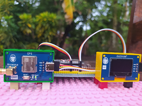
In this article, we will look at 0.96 OLED display using the MicroPython language. OLED stands for Organic Light Emitting Diode is a self-illuminating so backlight is not needed and more power efficient.
BILL OF MATERIALS:
- ESP32 development board.
- Gorillacell ESP32 shield (this is optional, you can directly connect to ESP32 if you don’t have this)
- 4-pin female-female Dupont jumper wires.
- Gorillacell 0.96 OLED display module.
PINOUT:
- GND – for the ground pin.
- VCC – for the supply voltage.
- SDA – for the i2c serial data pin.
- SCL – for the i2c serial clock pin.
HARDWARE INSTRUCTION:
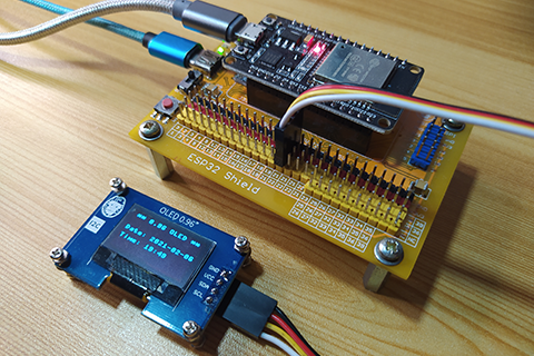
- First, attach the ESP32 development board at the top of ESP32 shield making sure that the USB ports are on the same sides.
- Next, attach the dupont jumper wires to the OLED display according to the color coding which is black for the GND, red for the VCC, yellow for the SDA, and white for the SCL.
- Next, attach the other side of the dupont jumper wires to the ESP32 shield by matching the colors of the pin headers and the colors of the jumper wires which is black to black, red to red, yellow and following colors to the yellow. In this tutorial, I choose GPIO 21 for the SDA and GPIO 22 for the SCL.
- Next, power the ESP32 shield by attaching an external power supply with a type-C USB cable and make sure that the power switch is slide to the ON state.
- Next, connect the ESP32 to the computer by attaching a micro USB cable. The demo circuit should now be ready.
SOFTWARE INSTRUCTION:
- In order to easily use the 0.96 OLED display, we need an external driver library. Thankfully, there is an available library from Adafruit which is the SSD1306.py: https://github.com/adafruit/micropython-adafruit-ssd1306/blob. Copy and paste it to the Thonny Python IDE.
- Save it to ESP32 MicroPython root directory by clicking the File menu, select Save As.
- Click the MicroPython device and save it as “ssd1306.py”. To check if you successfully save the OLED driver library, click the View menu and select File. The ssd1306.py should be seen under the MicroPython device.
VIDEO DEMONSTRATION:
CALL TO ACTION:
For any concern, write your message in the comment section.
You might also like to support my journey on Youtube by Subscribing. Click this to Subscribe to TechToTinker.
Thank you and have a good days ahead.
See you,
– George Bantique | tech.to.tinker@gmail.com
SOURCE CODE:
1. Example # 1, exploring the 0.96 OLED driver library using the REPL:
# More details can be found in TechToTinker.blogspot.com
# George Bantique | tech.to.tinker@gmail.com

from machine import Pin, I2C
from ssd1306 import SSD1306_I2C

i2c = I2C(scl=Pin(22), sda=Pin(21), freq=400000)
oled = SSD1306_I2C(128, 64, i2c, addr=0x3C)

# The following codes should be tested using the REPL.
# #1. To print a string:
# oled.text('Hello world', 0, 0)
# #2. To display all the commands in queue:
# oled.show()
# #3. Now to clear the oled display:
# oled.fill(0)
# oled.show()
# #4. You may also use the invert function to invert the display.
# oled.invert(1)
# #5.To display a single pixel.
# oled.pixel(10,20,1)
# oled.show()
# #6. To display a horizontal line
# oled.hline(30,40,10,1)
# oled.show()
# #7. To display a vertical line
# oled.vline(30,45,5,1)
# oled.show()
# #8. While hline and vline is quite useful, there is another function that is more flexible to use which is the line function.
# oled.line(0,50,10,50,1)
# oled.show()
# #9.We may also be able to print a rectangle.
# oled.rect(10,60,10,5,1)
# oled.show()
# #10. Or we may also print a filled rectangle:
# oled.fill_rect(10,70,10,5,1)
# oled.show()
2. Example # 2, displaying a Real Time Clock (RTC) using the ESP32’s builtin RTC module:
# More details can be found in TechToTinker.blogspot.com
# George Bantique | tech.to.tinker@gmail.com

from machine import Pin
from machine import I2C
from machine import RTC
from time import sleep_ms
from ssd1306 import SSD1306_I2C

i2c = I2C(scl=Pin(22), sda=Pin(21), freq=400000)
oled = SSD1306_I2C(128, 64, i2c, addr=0x3C)

rtc = RTC()
rtc.datetime((2021, 2, 6, 6, 19, 44, 0, 0))
# rtc.datetime((YYYY, MM, DD, WD, HH, MM, SS, MS))
# WD 1 = Monday
# WD 7 = Sunday
isPoint = True

while True:
    t = rtc.datetime()
    oled.fill(0)
    oled.text('** 0.96 OLED **', 4, 0)
    oled.text('Date: {}-{:02d}-{:02d}' .format(t[0],t[1],t[2]), 0, 25)
    if isPoint:
        colon = ':'
    else:
        colon = ' '
    oled.text('Time: {:02d}{}{:02d}' .format(t[4], colon, t[5]), 0, 40)
    oled.show()
    sleep_ms(500)
    isPoint = not isPoint
3. 0.96 OLED driver library
#MicroPython SSD1306 OLED driver, I2C and SPI interfaces created by Adafruit

import time
import framebuf

# register definitions
SET_CONTRAST        = const(0x81)
SET_ENTIRE_ON       = const(0xa4)
SET_NORM_INV        = const(0xa6)
SET_DISP            = const(0xae)
SET_MEM_ADDR        = const(0x20)
SET_COL_ADDR        = const(0x21)
SET_PAGE_ADDR       = const(0x22)
SET_DISP_START_LINE = const(0x40)
SET_SEG_REMAP       = const(0xa0)
SET_MUX_RATIO       = const(0xa8)
SET_COM_OUT_DIR     = const(0xc0)
SET_DISP_OFFSET     = const(0xd3)
SET_COM_PIN_CFG     = const(0xda)
SET_DISP_CLK_DIV    = const(0xd5)
SET_PRECHARGE       = const(0xd9)
SET_VCOM_DESEL      = const(0xdb)
SET_CHARGE_PUMP     = const(0x8d)


class SSD1306:
    def __init__(self, width, height, external_vcc):
        self.width = width
        self.height = height
        self.external_vcc = external_vcc
        self.pages = self.height // 8
        # Note the subclass must initialize self.framebuf to a framebuffer.
        # This is necessary because the underlying data buffer is different
        # between I2C and SPI implementations (I2C needs an extra byte).
        self.poweron()
        self.init_display()

    def init_display(self):
        for cmd in (
            SET_DISP | 0x00, # off
            # address setting
            SET_MEM_ADDR, 0x00, # horizontal
            # resolution and layout
            SET_DISP_START_LINE | 0x00,
            SET_SEG_REMAP | 0x01, # column addr 127 mapped to SEG0
            SET_MUX_RATIO, self.height - 1,
            SET_COM_OUT_DIR | 0x08, # scan from COM[N] to COM0
            SET_DISP_OFFSET, 0x00,
            SET_COM_PIN_CFG, 0x02 if self.height == 32 else 0x12,
            # timing and driving scheme
            SET_DISP_CLK_DIV, 0x80,
            SET_PRECHARGE, 0x22 if self.external_vcc else 0xf1,
            SET_VCOM_DESEL, 0x30, # 0.83*Vcc
            # display
            SET_CONTRAST, 0xff, # maximum
            SET_ENTIRE_ON, # output follows RAM contents
            SET_NORM_INV, # not inverted
            # charge pump
            SET_CHARGE_PUMP, 0x10 if self.external_vcc else 0x14,
            SET_DISP | 0x01): # on
            self.write_cmd(cmd)
        self.fill(0)
        self.show()

    def poweroff(self):
        self.write_cmd(SET_DISP | 0x00)

    def contrast(self, contrast):
        self.write_cmd(SET_CONTRAST)
        self.write_cmd(contrast)

    def invert(self, invert):
        self.write_cmd(SET_NORM_INV | (invert & 1))

    def show(self):
        x0 = 0
        x1 = self.width - 1
        if self.width == 64:
            # displays with width of 64 pixels are shifted by 32
            x0 += 32
            x1 += 32
        self.write_cmd(SET_COL_ADDR)
        self.write_cmd(x0)
        self.write_cmd(x1)
        self.write_cmd(SET_PAGE_ADDR)
        self.write_cmd(0)
        self.write_cmd(self.pages - 1)
        self.write_framebuf()

    def fill(self, col):
        self.framebuf.fill(col)

    def pixel(self, x, y, col):
        self.framebuf.pixel(x, y, col)

    def scroll(self, dx, dy):
        self.framebuf.scroll(dx, dy)

    def text(self, string, x, y, col=1):
        self.framebuf.text(string, x, y, col)

    # Missing from current files in github:
    # https://github.com/adafruit/micropython-adafruit-ssd1306/blob/master/ssd1306.py
    def hline(self, x, y, w, col):
        self.framebuf.hline(x, y, w, col)
    def vline(self, x, y, h, col):
        self.framebuf.vline(x, y, h, col)
    def line(self, x1, y1, x2, y2, col):
        self.framebuf.line(x1, y1, x2, y2, col)
    def rect(self, x, y, w, h, col):
        self.framebuf.rect(x, y, w, h, col)
    def fill_rect(self, x, y, w, h, col):
        self.framebuf.fill_rect(x, y, w, h, col)
    def blit(self, fbuf, x, y):
        self.framebuf.blit(fbuf, x, y)

class SSD1306_I2C(SSD1306):
    def __init__(self, width, height, i2c, addr=0x3c, external_vcc=False):
        self.i2c = i2c
        self.addr = addr
        self.temp = bytearray(2)
        # Add an extra byte to the data buffer to hold an I2C data/command byte
        # to use hardware-compatible I2C transactions.  A memoryview of the
        # buffer is used to mask this byte from the framebuffer operations
        # (without a major memory hit as memoryview doesn't copy to a separate
        # buffer).
        self.buffer = bytearray(((height // 8) * width) + 1)
        self.buffer[0] = 0x40  # Set first byte of data buffer to Co=0, D/C=1
        self.framebuf = framebuf.FrameBuffer1(memoryview(self.buffer)[1:], width, height)
        super().__init__(width, height, external_vcc)

    def write_cmd(self, cmd):
        self.temp[0] = 0x80 # Co=1, D/C#=0
        self.temp[1] = cmd
        self.i2c.writeto(self.addr, self.temp)

    def write_framebuf(self):
        # Blast out the frame buffer using a single I2C transaction to support
        # hardware I2C interfaces.
        self.i2c.writeto(self.addr, self.buffer)

    def poweron(self):
        pass

class SSD1306_SPI(SSD1306):
    def __init__(self, width, height, spi, dc, res, cs, external_vcc=False):
        self.rate = 10 * 1024 * 1024
        dc.init(dc.OUT, value=0)
        res.init(res.OUT, value=0)
        cs.init(cs.OUT, value=1)
        self.spi = spi
        self.dc = dc
        self.res = res
        self.cs = cs
        self.buffer = bytearray((height // 8) * width)
        self.framebuf = framebuf.FrameBuffer1(self.buffer, width, height)
        super().__init__(width, height, external_vcc)

    def write_cmd(self, cmd):
        self.spi.init(baudrate=self.rate, polarity=0, phase=0)
        self.cs.high()
        self.dc.low()
        self.cs.low()
        self.spi.write(bytearray([cmd]))
        self.cs.high()

    def write_framebuf(self):
        self.spi.init(baudrate=self.rate, polarity=0, phase=0)
        self.cs.high()
        self.dc.high()
        self.cs.low()
        self.spi.write(self.buffer)
        self.cs.high()

    def poweron(self):
        self.res.high()
        time.sleep_ms(1)
        self.res.low()
        time.sleep_ms(10)
        self.res.high()
REFERENCES AND CREDITS:
1. Adafruit SSD1306: https://github.com/adafruit/micropython-adafruit-ssd1306/blob
2. Gorillacell ESP32 kit: gorillacell.kr
how can i increase font size in this 0.96 0led display
Watch it from here: https://www.youtube.com/watch?v=YogBioKLrh4
Regards.