

025 – MicroPython TechNotes: Joystick
In this article, we will tackle how to use JOYSTICK with ESP32 using MicroPython programming language.
PINOUT:
- G – for the ground pin.
- V – for the supply voltage.
- x – for the horizontal potentiometer pin.
- y – for the vertical potentiometer pin.
BILL OF MATERIALS:
- ESP32 development board to serve as the brain for the experiment.
- ESP32 shield from Gorillacell ESP32 development kit to extend the ESP32 pins to pin headers for easy circuit connection.
- 4-pin female-female dupont jumper wires to connect the joystick module to the ESP32 shield.
- Joystick module itself.
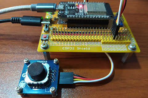
HARDWARE INSTRUCTION:
- First, attach the ESP32 development board on top of the ESP32 shield and make sure that both USB ports are on the same side.
- Next, attach the dupont wires to the joystick module by following the color coding which is black for the ground, red for the VCC, yellow for the x pin, and white for the y pin.
- Next, attach the other end of the dupont wires to the ESP32 shield by matching the colors of the wires to the colors of the pin headers which is black to black, red to red, yellow and the following colors to the yellow pin headers.
- Next, power the ESP32 shield with an external power supply with a type-C USB connector and make sure that the power switch is set to ON state.
- Lastly, connect the ESP32 to the computer through a micro-USB cable. Our demo circuit should be now ready.
SOFTWARE INSTRUCTION:
I prepared 3 example source code for this demo.
Copy and paste it to your Thonny IDE.
Play with it, modify and adapt according to your needs.
Enjoy and happy tinkering.
VIDEO DEMONSTRATION:
For any concern, write your message in the comment section.
You might also like to support my journey on Youtube by Subscribing. Click this to Subscribe to TechToTinker.
Thank you and have a good days ahead.
See you,
– George Bantique | tech.to.tinker@gmail.com
SOURCE CODE:
1. Example # 1, basics of reading an analog input just like the joystick module:
# More details can be found in TechToTinker.blogspot.com
# George Bantique | tech.to.tinker@gmail.com

from machine import Pin, ADC
from time import sleep_ms

x = ADC(Pin(32, Pin.IN))
y = ADC(Pin(33, Pin.IN))
x.atten(ADC.ATTN_11DB)
y.atten(ADC.ATTN_11DB)

while True:
    x_val = x.read()
    y_val = y.read()
    print('Current position:{},{}'.format(x_val,y_val))
    sleep_ms(300)
How the code works:
from machine import Pin, ADC
Imports Pin class and ADC class from machine module. Pin class is use to access the ESP32 pins. ADC class is use in order to read analog pin.
from time import sleep_ms
Imports sleep_ms class from time module in order to create delays in milliseconds resolution.
x = ADC(Pin(32, Pin.IN))
y = ADC(Pin(33, Pin.IN))
x.atten(ADC.ATTN_11DB)
y.atten(ADC.ATTN_11DB)
Creates ADC objects for the joystick module named x and y. x is connected to GPIO 32 with a pin direction set as input. y is connected to GPIO 33 with a pin direction set as input. For the ADC, we use an attenuation of 11 dB in order to use 0V to 3.3V logic level.
while True:
Creates an infinite loop.
x_val = x.read()
y_val = y.read()
print(‘Current position:{},{}’.format(x_val,y_val))
Reads the analog value of the pins for the x and y and stored it to x_val and y_val variables and prints it to the REPL.
sleep_ms(300)
Creates a 300 milliseconds interval
2. Example # 2, display joystick position using RGB matrix:
# More details can be found in TechToTinker.blogspot.com
# George Bantique | tech.to.tinker@gmail.com

from machine import Pin, ADC
from neopixel import NeoPixel
from time import sleep_ms

class RGB_Matrix:

    def __init__(self, gpio, width, height):
        self.width = width
        self.height = height
        self.neopixel = NeoPixel(Pin(gpio), width*height)

    def pixel_set(self, row, col, r=0, g=0, b=0):
        self.neopixel[row + (col*self.width)] = (r, g, b)
        self.neopixel.write()

    def pixel_clr(self, row, col):
        self.neopixel[row + (col*self.width)] = (0, 0, 0)
        self.neopixel.write()

    def clear_all(self):
        self.neopixel.fill((0,0,0))
        self.neopixel.write()


np = RGB_Matrix(25, 8, 8)
x = ADC(Pin(32, Pin.IN))
y = ADC(Pin(33, Pin.IN))
x.atten(ADC.ATTN_11DB)
y.atten(ADC.ATTN_11DB)

def map(x, in_min, in_max, out_min, out_max):
    # This will not handle x value greater than in_max or
    #                      x value less than in_min
    return int((x - in_min) * (out_max - out_min) / (in_max - in_min) + out_min)

while True:
    x_pos = map(x.read(), 0, 4095, 0, 7)
    y_pos = map(y.read(), 0, 4095, 7, 0)
    np.clear_all()
    np.pixel_set(x_pos, y_pos, 10,0,0)
    sleep_ms(300)
How the code works:
x_pos = map(x.read(), 0, 4095, 0, 7)
y_pos = map(y.read(), 0, 4095, 7, 0)
Reads the analog values from the joystick module which have a value ranging from 0 to 4095 and convert it to 0 to 7 by ratio and proportion by calling the map() function. Please be noted that y position is rotated.
np.clear_all()
Clears all the RGB LED pixels.
np.pixel_set(x_pos, y_pos, 10,0,0)
Set specific RGB LED according to the converted x and y position.
3. Example # 3, control a pixel in RGB matrix using the joystick module:
# More details can be found in TechToTinker.blogspot.com
# George Bantique | tech.to.tinker@gmail.com

from machine import Pin, ADC
from neopixel import NeoPixel
from time import sleep_ms

class RGB_Matrix:

    def __init__(self, gpio, width, height):
        self.width = width
        self.height = height
        self.neopixel = NeoPixel(Pin(gpio), width*height)

    def pixel_set(self, row, col, r=0, g=0, b=0):
        self.neopixel[row + (col*self.width)] = (r, g, b)
        self.neopixel.write()

    def pixel_clr(self, row, col):
        self.neopixel[row + (col*self.width)] = (0, 0, 0)
        self.neopixel.write()

    def clear_all(self):
        self.neopixel.fill((0,0,0))
        self.neopixel.write()


np = RGB_Matrix(25, 8, 8)
x = ADC(Pin(32, Pin.IN))
y = ADC(Pin(33, Pin.IN))
x.atten(ADC.ATTN_11DB)
y.atten(ADC.ATTN_11DB)

curr_x = 3
curr_y = 3

while True:
    x_val = x.read()
    y_val = y.read()

    if x_val < 1850:
      if curr_x > 0:
        curr_x = curr_x - 1
    elif x_val > 1930:
      if curr_x < 7:
        curr_x = curr_x + 1
    if y_val < 1890:
      if curr_y < 7:
        curr_y = curr_y + 1
    elif y_val > 1970:
      if curr_y > 0:
        curr_y = curr_y - 1
    print(curr_x, curr_y)

    np.clear_all()
    np.pixel_set(curr_x, curr_y, 10, 0, 0)
    sleep_ms(100)
How the code works:
if x_val < 1850:
if curr_x > 0:
curr_x = curr_x – 1
elif x_val > 1930:
if curr_x < 7:
curr_x = curr_x + 1
if y_val < 1890:
if curr_y < 7:
curr_y = curr_y + 1
elif y_val > 1970:
if curr_y > 0:
curr_y = curr_y – 1
print(curr_x, curr_y)
Checks if joystick has been move to any direction. If yes, also check if the current position is not in the border line before adding or subtracting from the current position.
np.clear_all()
Clears all the pixel in the RGB LED by turning it OFF.
np.pixel_set(curr_x, curr_y, 10, 0, 0)
Then set the specific RGB pixel according to the current position set by the joystick module.
REFERENCES AND CREDITS:
1. Purchase your Gorillacell ESP32 development kit at:
Very good instruction video ! Right what I needed. Thanks.
@Vliegvogeltla, I am glad that you useful. Thanks.