005 - MicroPython TechNotes: Gorilla Cell LED | MicroPython Hello World
Introduction
In this article, we will look at LED. We will learn on how to control it by turning it ON and OFF. LED stands for Light-Emitting Diode. It is a type of electronic of component that emits light when a sufficient voltage is applied on its terminals.
Pinout
- G – for the ground pin.
- V – for the supply voltage pin.
- S – for the control signal for the LED. Applying a logic 1 on this pin will turn ON the LED and a logic 0 turn it OFF.
Bill Of Materials
- LED module.
- ESP32 Development board.
- Gorilla ESP32 shield.
- 3-pin female-to-female dupont jump wires.
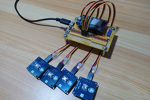
Hardware Instruction
- Connect ESP32 dev board at the top of ESP32 shield observing correct orientation and alignment.
- Attach a dupont to LED module observing proper color-coding which black wire for the ground, red wire for the VCC, and yellow wire for other signal pins.
- Attach the other side of dupont to ESP32 shield by matching the color-coding of the dupont and the pin headers which black to black, red to red, and other colors to yellow.
- Power up the ESP32 shield by attaching the USB type-C cable.
- Connect the micro USB cable to ESP32 dev board.

Software Instruction
- Open Thonny Python IDE.
- Click “New” to create a new file.
- Copy and paste one of the example source code.
- Save it to your computer in your preferred location. I recommend to create a single folder location for easy reference.
- Click the “Stop” button in Thonny. The triple greater than sign should appear >>>.
- Click the “Run” button to execute the code.
- Enjoy.
Video Demonstration
Call To Action
For any concern, write your message in the comment section.
You might also like to support my journey on Youtube by Subscribing. Click this to Subscribe to TechToTinker.
Thank you and have a good days ahead.
See you,
– George Bantique | tech.to.tinker@gmail.com
Source Code
1. LED Example # 1, turning ON or OFF:
 1from machine import Pin
 2
 3red = Pin(16, Pin.OUT)
 4
 5# The following codes should be tested
 6# using the REPL
 7red.on()  # Turn ON LED
 8red.off() # Turn OFF LED
 9
10red.value(1) # Turn ON LED
11red.value(0) # Turn OFF LED
12
13red.value(True)  # Turn ON LED
14red.value(False) # Turn OFF LED
How the code works:
from machine import Pin
This imports or loads the Pin class from the machine module to enable access to the ESP32 pins.
red = Pin(16, Pin.OUT)
Creates an object named “red” for the red LED which connected on GPIO 16 denoted by the number “16” and the pin is set as an output by “Pin.OUT”.
The red LED can be turned ON by calling any of the following: red.on() red.value(1) red.value(True)
or turn it OFF by calling any of the following: red.off() red.value(0) red.value(False)
2. LED Example#2, blinking all LED:
 1from machine import Pin
 2from time import sleep
 3
 4r = Pin(16, Pin.OUT)
 5g = Pin(17, Pin.OUT)
 6b = Pin(18, Pin.OUT)
 7y = Pin(19, Pin.OUT)
 8
 9while True:
10    # Turn ON 'all' LEDs
11    r.on()
12    g.on()
13    b.on()
14    y.on()
15    sleep(1)
16
17    # Turn OFF 'all' LEDs
18    r.off()
19    g.off()
20    b.off()
21    y.off()
22    sleep(1)
How the code works:
1from machine import Pin
2from time import sleep
This imports the Pin class from the machine library and the sleep class from the time library. Pin class enables access to the pins of ESP32 while sleep class enables the use of sleep() function which is equivalent to delay.
1r = Pin(16, Pin.OUT)
2g = Pin(17, Pin.OUT)
3b = Pin(18, Pin.OUT)
4y = Pin(19, Pin.OUT)
Creates objects for the LEDs namely “r” for the red LED, “g” for the green LED, “b” for the blue LED, and “y” for the yellow LED.
 1while True:
 2    r.on()
 3    g.on()
 4    b.on()
 5    y.on()
 6    sleep(1)
 7    r.off()
 8    g.off()
 9    b.off()
10    y.off()
11    sleep(1)
Creates the main loop of the program. “while True:” makes the loop to loop forever or indefinitely. Any code inside will be executed one by one until the end then the cycle will be repeated.
Inside the main loop, all the LEDs are turned ON then it will wait for 1 second before turning it OFF then wait for another 1 second then the program will be repeated.
3. LED Example#3, running LED:
 1from machine import Pin
 2from time import sleep
 3
 4r = Pin(16, Pin.OUT)
 5g = Pin(17, Pin.OUT)
 6b = Pin(18, Pin.OUT)
 7y = Pin(19, Pin.OUT)
 8
 9# Create the list of led objects
10led = [r, g, b, y]
11while True:
12    # Create a loop that will iterate from 0 to 3
13    for x in range(4):
14        print(x)       # Print the current value of 'x'
15        led[x].on()    # Turn ON current x led
16        led[x-1].off() # Turn OFF previous x led
17        sleep(0.5)     # Stay in the LED value for a definite time
How the code works:
The works similar to example # 2 but this time, it is turned ON one-by-one to create the running-LED-effect.
1led = \[r, g, b, y\]
Creates the list of LED objects which works similar to an array.
Inside the main loop, the LEDs are turned on one-by-one by using the for loop and turned on the LED according to current loop index.
References And Credits
Posts in this series
- 049 - MicroPython TechNotes: MP3 Player
- 048 - MicroPython TechNotes: Analog Touch Sensor
- 047 - MicroPython TechNotes: E108 GPS
- 046 - MicroPython TechNotes: RF433 Transceivers
- 045 - MicroPython TechNotes: Infrared Transmitter
- 044 - MicroPython TechNotes: Infrared Receiver
- 043 - MicroPython TechNotes: ESP12E WiFi | External WiFi module
- 042 - MicroPython TechNotes: JDY-32 | Bluetooth Low Energy BLE
- 041 - MicroPython TechNotes: Bluetooth HC-06
- 040 - MicroPython TechNotes: Relay
- 039 - MicroPython TechNotes: Electromagnet
- 038 - MicroPython TechNotes: Buzzer
- 037 - MicroPython TechNotes: Servo Motor
- 036 - MicroPython TechNotes: Stepper Motor
- 035 - MicroPython TechNotes: Dual Motor Driver
- 034 - MicroPython TechNotes: DC Motors | Gear Motor and Fan Motor
- 033 - MicroPython TechNotes: TCS34725 RGB Color Sensor
- 032 - MicroPython TechNotes: BMP280 Sensor
- 031 - MicroPython TechNotes: TOF Distance Sensor
- 030 - MicroPython TechNotes: DS3231 RTC
- 029 - MicroPython TechNotes: HC-SR04 Ultrasonic Sensor
- 028 - MicroPython TechNotes: DHT11 Temperature and Humidity Sensor
- 027 - MicroPython TechNotes: Rotary Encoder
- 026 - MicroPython TechNotes: Light Dependent Resistor (LDR)
- 025 - MicroPython TechNotes: Joystick
- 024 - MicroPython TechNotes: Slider Switch
- 023 - MicroPython TechNotes: Continuous Rotation Potentiometer
- 022 - MicroPython TechNotes: Potentiometer | Reading an Analog Input
- 021 - MicroPython TechNotes: Color Touch Sensor
- 020 - MicroPython TechNotes: Touch Sensor
- 019 - MicroPython TechNotes: Switch Module
- 018 - MicroPython TechNotes: Button | Reading an Input
- 017 - MicroPython TechNotes: LASER Module
- 016 - MicroPython TechNotes: RGB LED Matrix
- 015 - MicroPython TechNotes: Neopixel 16
- 014 - MicroPython TechNotes: 8x8 Dot Matrix Display (I2C)
- 013 - MicroPython TechNotes: 8x16 Dot Matrix Display (SPI)
- 012 - MicroPython TechNotes: 8x8 Dot Matrix Display (SPI)
- 011 - MicroPython TechNotes: 1.3 OLED Display
- 010 - MicroPython TechNotes: 0.96 OLED Display
- 009 - MicroPython TechNotes: 7 Segment Display
- 008 - MicroPython TechNotes: 16x2 LCD
- 007 - MicroPython TechNotes: RGB LED
- 006 - MicroPython TechNotes: Traffic Light LED Module
- 004 - MicroPython TechNotes: Gorilla Cell I/O Devices
- 003 - MicroPython TechNotes: Gorillacell ESP32 Shield
- 002 - MicroPython TechNotes: Introduction for Gorillacell ESP32 Dev Kit
- 001 - MicroPython TechNotes: Get Started with MicroPython
- 000 - MicroPython TechNotes: Unboxing Gorillacell ESP32 Development Kit
No comments yet!