007 - MicroPython TechNotes: RGB LED
Introduction
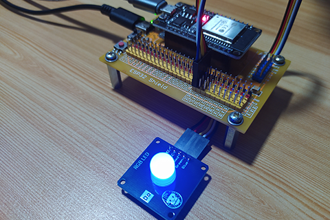
In this article, we will look at RGB LED module. We will learn on how to use it to create cool and amazing projects.
Pinout
- GND – for the ground pin.
- VCC – for the supply voltage pin.
- Red – for the control signal of the red LED.
- Green – for the control signal of the green LED.
- Blue – for the control signal of the blue LED.
Bill Of Materials
- ESP32 development board.
- Gorilla Cell ESP32 shield (optional).
- 5-pin dupont jumper wires.
- RGB LED module.
Hardware Instruction
- Attach the ESP32 development board on top of the Gorilla Cell ESP32 shield making sure that the pins are aligned and the both the USB port are on the same side, in my case it is in the left-hand side.
- Attach the dupont jumper wires to RGB LED module according to the following color coding:
- black for the Ground.
- red for the VCC.
- yellow for the Red pin.
- white for the Green pin.
- blue for the Blue pin.
- Attach the other side of the dupont jumper wires to the ESP32 by matching the colors of the dupont wires and the colors of the pin headers.
- Attach a type-C USB cable to the ESP32 shield for external power supply.
- Connect the ESP32 to computer by attaching a micro USB cable.
Software Instruction
- Open the Thonny Python IDE. If you don’t have this installed, be sure to watch the article tutorial number 1.
- Press the “Stop” button to let the Thonny Python IDE to connect to ESP32.
- Create a new Python file by clicking the “New” button.
- Copy and paste the provided source code below to your Thonny.
- Press “Run the current script” to execute the code.
- Enjoy and feel free to modify it according to your liking.
Video Demonstration
Call To Action
For any concern, write your message in the comment section.
You might also like to support my journey on Youtube by Subscribing. Click this to Subscribe to TechToTinker.
Thank you and have a good days ahead.
See you,
– George Bantique | tech.to.tinker@gmail.com
Source Code
1. Example # 1, RGB basic ON or OFF:
 1from machine import Pin
 2
 3r = Pin(23, Pin.OUT)
 4g = Pin(25, Pin.OUT)
 5b = Pin(26, Pin.OUT)
 6
 7# The following code should be tested using the REPL
 8
 9# r.on()  # Turn ON red LED.
10# r.off() # Turn OFF red LED.
11# g.value(1) # Turn ON green LED.
12# g.value(0) # Turn OFF green LED.
13# b.value(True)  # Turn ON blue LED.
14# b.value(False) # Turn OFF blue LED.
py
2. Example # 2, basic RGB color combination:
 1from machine import Pin, PWM
 2
 3r = Pin(23, Pin.OUT)
 4g = Pin(25, Pin.OUT)
 5b = Pin(26, Pin.OUT)
 6
 7def set_rgb(x, y, z):
 8    r.value(x)
 9    g.value(y)
10    b.value(z)
11
12def rst_rgb():
13    r.off()
14    g.off()
15    b.off()
16
17# The following code should be tested using the REPL.
18
19# This is to demonstrate for creating colors:
20# set_rgb(1,0,0) # red
21# set_rgb(0,1,0) # green
22# set_rgb(0,0,1) # blue
23# Or a combination of primary colors:
24# set_rgb(1,1,0) # r + g = yellow
25# set_rgb(0,1,1) # g + b = cyan
26# set_rgb(1,0,1) # r + b = magenta
27# set_rgb(1,1,1) # r+g+b = white
py
3. Example # 3, advance RGB color combination:
 1from machine import Pin, PWM
 2
 3r = PWM(Pin(23))
 4g = PWM(Pin(25))
 5b = PWM(Pin(26))
 6
 7# Initialize the PWM frequency to 60Hz
 8r.freq(60)
 9g.freq(60)
10b.freq(60)
11
12# and Initialize with pulse turned OFF
13r.duty(0)
14g.duty(0)
15b.duty(0)
16
17def map(x, in_min, in_max, out_min, out_max):
18    # This will not handle x value greater than in_max or
19    #                      x value less than in_min
20    return int((x - in_min) * (out_max - out_min) / (in_max - in_min) + out_min)
21def set_rgb(x, y, z):
22    # Maximum duty cycle is 1023
23    # RGB values is usually 0 to 255
24    # By using ratio and proportion
25    r.duty(map(x, 0, 255, 0, 1023))
26    g.duty(map(y, 0, 255, 0, 1023))
27    b.duty(map(z, 0, 255, 0, 1023))
28
29def rst_rgb():
30    # Turn off all pwm pulse
31    r.duty(0)
32    g.duty(0)
33    b.duty(0)
34
35# The following code should be tested using the REPL.
36
37# This is to demonstrate for creating colors:
38# set_rgb(255,0,0) # red
39# set_rgb(0,255,0) # green
40# set_rgb(0,0,255) # blue
41# Or a combination of primary colors:
42# set_rgb(255,255,0) # r + g = yellow
43# set_rgb(0,255,255) # g + b = cyan
44# set_rgb(255,0,255) # r + b = magenta
45# set_rgb(255,255,255) # r+g+b = white
py
4. Example # 4, breathing RGB color:
 1from machine import Pin, PWM
 2from time import sleep
 3
 4r = PWM(Pin(23))
 5g = PWM(Pin(25))
 6b = PWM(Pin(26))
 7
 8# Initialize the PWM frequency to 60Hz
 9r.freq(60)
10g.freq(60)
11b.freq(60)
12# and Initialize with pulse turned OFF
13r.duty(0)
14g.duty(0)
15b.duty(0)
16
17while True:
18    for i in range(1024):
19        r.duty(i)
20        #g.duty(i)
21        #b.duty(i)
22        sleep(0.001)
23
24    for i in range(1023, -1, -1):
25        r.duty(i)
26        #g.duty(i)
27        #b.duty(i)
28        sleep(0.001)
py
References And Credits
- Purchased your kit at: gorillacell.kr
Posts in this series
- 049 - MicroPython TechNotes: MP3 Player
- 048 - MicroPython TechNotes: Analog Touch Sensor
- 047 - MicroPython TechNotes: E108 GPS
- 046 - MicroPython TechNotes: RF433 Transceivers
- 045 - MicroPython TechNotes: Infrared Transmitter
- 044 - MicroPython TechNotes: Infrared Receiver
- 043 - MicroPython TechNotes: ESP12E WiFi | External WiFi module
- 042 - MicroPython TechNotes: JDY-32 | Bluetooth Low Energy BLE
- 041 - MicroPython TechNotes: Bluetooth HC-06
- 040 - MicroPython TechNotes: Relay
- 039 - MicroPython TechNotes: Electromagnet
- 038 - MicroPython TechNotes: Buzzer
- 037 - MicroPython TechNotes: Servo Motor
- 036 - MicroPython TechNotes: Stepper Motor
- 035 - MicroPython TechNotes: Dual Motor Driver
- 034 - MicroPython TechNotes: DC Motors | Gear Motor and Fan Motor
- 033 - MicroPython TechNotes: TCS34725 RGB Color Sensor
- 032 - MicroPython TechNotes: BMP280 Sensor
- 031 - MicroPython TechNotes: TOF Distance Sensor
- 030 - MicroPython TechNotes: DS3231 RTC
- 029 - MicroPython TechNotes: HC-SR04 Ultrasonic Sensor
- 028 - MicroPython TechNotes: DHT11 Temperature and Humidity Sensor
- 027 - MicroPython TechNotes: Rotary Encoder
- 026 - MicroPython TechNotes: Light Dependent Resistor (LDR)
- 025 - MicroPython TechNotes: Joystick
- 024 - MicroPython TechNotes: Slider Switch
- 023 - MicroPython TechNotes: Continuous Rotation Potentiometer
- 022 - MicroPython TechNotes: Potentiometer | Reading an Analog Input
- 021 - MicroPython TechNotes: Color Touch Sensor
- 020 - MicroPython TechNotes: Touch Sensor
- 019 - MicroPython TechNotes: Switch Module
- 018 - MicroPython TechNotes: Button | Reading an Input
- 017 - MicroPython TechNotes: LASER Module
- 016 - MicroPython TechNotes: RGB LED Matrix
- 015 - MicroPython TechNotes: Neopixel 16
- 014 - MicroPython TechNotes: 8x8 Dot Matrix Display (I2C)
- 013 - MicroPython TechNotes: 8x16 Dot Matrix Display (SPI)
- 012 - MicroPython TechNotes: 8x8 Dot Matrix Display (SPI)
- 011 - MicroPython TechNotes: 1.3 OLED Display
- 010 - MicroPython TechNotes: 0.96 OLED Display
- 009 - MicroPython TechNotes: 7 Segment Display
- 008 - MicroPython TechNotes: 16x2 LCD
- 006 - MicroPython TechNotes: Traffic Light LED Module
- 005 - MicroPython TechNotes: Gorilla Cell LED | MicroPython Hello World
- 004 - MicroPython TechNotes: Gorilla Cell I/O Devices
- 003 - MicroPython TechNotes: Gorillacell ESP32 Shield
- 002 - MicroPython TechNotes: Introduction for Gorillacell ESP32 Dev Kit
- 001 - MicroPython TechNotes: Get Started with MicroPython
- 000 - MicroPython TechNotes: Unboxing Gorillacell ESP32 Development Kit
No comments yet!