Tutorial: Arduino GPIO | How to use Arduino Pins
Introduction
When I am starting to learn the Arduino microcontroller, I started searching on how I am able to use it immediately because I believe that the best way of learning something is the experience of using it.
In this tutorial, we will learn the basics of Arduino GPIO or the General Purpose Input Output or in the simplest term Arduino pins.
GPIO are physical pins found in microcontrollers which can be configured either as input or output.
When a certain pin is configured as input, it can be used to read the state of a switch or the value of the sensor.
When a certain pin is configured as output, it can be used to write such as lights ON or lights OFF or control the rotation of DC motors.
Now let us discuss functions commonly used in Arduino:

This function is use to set the direction of the PIN either as input or output.
Example:
This configures digital pin 13 as output.
OUTPUT mode configures the PIN output which can drive LEDs, LCD, control signals, and etcetera. INPUT mode configures the PIN as input which can read state of switch or read sensor data. An external pull-down or pull-up resistor is needed when the input pin has unknown state which also known as tri-state. INPUT_PULLUP mode configures the PIN as input and also connects the PIN to a pullup resistor internally. This is especially useful when external pullup or pulldown resistor is not available. Pull-up Resistor – is a resistor connected between the VCC and the specific pin. Pullup resistor makes the specific pin to a default value of logic HIGH. The RESET button of Arduino Uno is configured using a pullup resistor, so the default value is logic HIGH but when the RESET button is pressed, the RESET button will be connected to the GND which has logic LOW value.
(insert pullup vs pulldown resistor)
Pull-down Resistor – is a resistor connected between the GND and the specific pin. It function similar to pull-up resistor but opposite logic functions. (show the benefit of pull-up resistor by showing the state of a pin when floating and when pullup.)
digitalWrite(PIN, HIGH/LOW) This function drives the PIN either a logic HIGH or logic LOW.
digitalRead(PIN) This function reads the state of the PIN and return either a logic HIGH or logic LOW.

analogWrite(PIN, VALUE) This function writes an analog value (in PWM square wave) to a pin.

analogRead(PIN) This function reads an analog value from a specified analog pins.
Circuit Diagram
(insert circuit diagram here)
Video Demonstration
Source Code
1#include "Servo.h"
2#include "LiquidCrystal.h"
3
4#define RED_LED_PIN 11
5#define YEL_LED_PIN 12
6#define SERVO_PIN A5
7
8#define JS_YL_PIN A1 // Joystick vertical position in the left
9#define JS_XL_PIN A2 // Joystick horizontal position in the left
10#define JS_YR_PIN A3 // Joystick vertical position in the right
11#define JS_XR_PIN A4 // Joystick horizontal position in the right
12
13#define JS_SL_PIN 3 // Joystick tactile switch in the left
14#define JS_SR_PIN 2 // Joystick tactile switch in the right
15
16Servo myservo;
17LiquidCrystal lcd(8, 9, 4, 5, 6, 7);
18
19void setup() {
20
21 // Setting of the pin direction
22 pinMode(RED_LED_PIN, OUTPUT);
23 pinMode(YEL_LED_PIN, OUTPUT);
24 pinMode(SERVO_PIN, OUTPUT);
25
26 pinMode(JS_YL_PIN, INPUT);
27 pinMode(JS_XL_PIN, INPUT);
28 pinMode(JS_YR_PIN, INPUT);
29 pinMode(JS_XR_PIN, INPUT);
30
31 pinMode(JS_SL_PIN, INPUT_PULLUP);
32 pinMode(JS_SR_PIN, INPUT_PULLUP);
33
34 // ##########################
35 myservo.attach(SERVO_PIN); // Attach the servo to the assigned pin
36 lcd.begin(16,2); // Initialize the LCD as 16 columns and 2 rows
37 lcd.clear(); // Clear any garbage in the LCD EPROM
38
39}
40
41void loop() {
42
43 //#######################################
44 // Using the horizontal (X) analog value
45 int js_xr_value = analogRead(JS_XR_PIN);
46 byte servo_angle = map (js_xr_value, 0, 1023, 0, 180);
47 myservo.write(servo_angle);
48 lcd.setCursor(0,0);
49 lcd.print("Servo angle: ");
50 if (servo_angle < 100) { // if value is 0 to 99, add a space before printing
51 lcd.print(" "); // this is to make sure that 3 digits is occupied always
52 }
53 lcd.print(servo_angle);
54
55 //#######################################
56 // Using the vertical (Y) analog value
57 int js_yr_value = analogRead(JS_YR_PIN);
58 byte led_pwm = map ( js_yr_value, 0, 1023, 255, 0);
59 analogWrite(RED_LED_PIN, led_pwm);
60
61 lcd.setCursor(0,1);
62 lcd.print("LED pwm: ");
63 if (led_pwm < 100) { // if value is 0 to 99, add space before printing
64 lcd.print(" "); // this is to make sure that 3 digits is occupied always.
65 }
66 lcd.print(led_pwm);
67
68 //#################################################
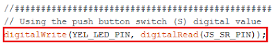
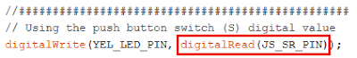
69 // Using the push button switch (S) digital value
70 digitalWrite(YEL_LED_PIN, digitalRead(JS_SR_PIN));
71
72}
Call To Action
That’s all for now, I hope this tutorial helps. Please kindly LIKE and SHARE this video to your friends who may benefit from it. SUBSCRIBE and leave your comments and suggestions in the comment box. Thank you and have a good day. George signing off, bye.
Posts in this series
- How to Get Started with ATTiny85 in Arduino IDE
- Tutorial: How to use MFRC522 RFID module using Arduino
- SOS Flasher Using Millis Function with Enable Switch
- Tutorial: How to use DS3231 RTC in Arduino
- Tutorial: How to use 0.96 OLED - a small and cute display
- Tutorial: Getting Started with the NRF24L01 | How to use | Arduino
- Tutorial: How to use SIM800L GSM Module for Controlling Anything | Arduino
- Tutorial: How to use Keypad | Text Entry Mode | Arduino
- Tutorial: How to use 4x4 Keypad | Arduino
- Project Idea: Arduino Voltmeter
- Project Idea: Door Lock Security | Arduino
- Multitasking with Arduino | Relay Timer Controller | using millis
- Tutorial Understanding Blink Without Delay | How to millis
- Arduino Simple LCD Menu
- How to use SIM800L GSM Module using Arduino | Make or Answer Voice Calls
- Tutorial: How to Use Arduino Uno as HID | Part 2: Arduino Mouse Emulation
- Tutorial: How to Use Arduino Uno as HID | Part 1: Arduino Keyboard Emulation
- Tutorial: How to use SIM800L DTMF to Control Anything | Arduino
- Tutorial: Arduino EEPROM
- How to use SIM800L GSM Module | Arduino | Send and Receive SMS
- 16x2 LCD Menu for Arduino
- MIT App Inventor for Arduino
- RC Car using L298N, HC-06, and Arduino Uno
- How to Use LCD Keypad Shield for Arduino
- How to Use Arduino Interrupts
- Project: Automatic Alcohol Dispenser
- TUTORIAL: How to use HC-SR04 Ultrasonic Sensor with Arduino
- Source Code: Astronomia Meme and Funeral Dance | melodies the Arduino way
- How to Get Started with L293D Motor Driver Shield with Arduino
- How to Get Started with L298N Motor Driver module using Arduino
- Part 2: Wav Music Player with Lyrics Using Arduino and SD Card
- Interfacing Infrared to Arduino Uno
- Part 1: Wav Music Player Using Arduino Uno and SD Card
- How to Interface Stepper Motor to Arduino Uno
- How To Play MP3 Files on Arduino from SD Card
- What is Arduino Software Serial
- How to Interface SD card to Arduino (without SD card shield)?
- Playing Melodies Using Arduino
- 8 Degrees Of Freedom (DOF) Robot Using Arduino Uno
- How to Interface PS2 Controller to Arduino Uno
- Part 3: DF Player Mini Tinkering with Arduino Nano and LCD
- How to Interface HC-06 to Arduino
- How to make a Remote Control RC car using Arduino and HC-06 bluetooth module
- Part 2: DF Player Mini Tinkering with Arduino Nano
- Part 1: DF Player Mini - a mini cheap mp3 player
No comments yet!