Tutorial: Getting Started with the NRF24L01 | How to use | Arduino
Introduction
NRF24L01 is one of the cheapest wireless radio module available in the market. In here you will learn how to interface it to Arduino and use it for controlling something remotely.
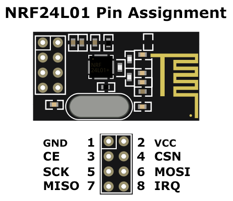
Pin Assignment
Circuit Diagram

Hardware Instruction
- Connect the NRF GND pin 1 to Arduino Uno GND pin
- Connect the NRF VCC pin 2 to Arduino Uno 3.3V pin
- Connect the NRF CE pin 3 to Arduino Uno digital pin 9
- Connect the NRF CSN pin 4 to Arduino Uno digital pin 8
- Connect the NRF SCK pin 5 to Arduino Uno digital pin 13
- Connect the NRF MOSI pin 6 to Arduino Uno digital pin 11
- Connect the NRF MISO pin 7 to Arduino Uno digital pin 12
- Connect the NRF IRQ pin 8 to Arduino Uno digital pin 10, we will not use
For node A:
9. Connect an LED with limiting resistor to Arduino Uno analog pin A0
10. Connect 3pcs of tactile switch buttons to Arduino Uno analog pins A1, A2, and A3. The other pins of the switch should be connected to the ground for an active LOW logic. Internal pullup will be use.
For node B:
11. Connect the signal pin of the servo motor to the Arduino Uno digital pin 6 PWM output. Servo motor VCC and GND pin will be connected to Arduino Uno 5V pin and GND. This is ok to do if you have a small servo but you may also use external power supply for the servo.
12. Connect a tactile switch button to Arduino Uno digital pin 5. The other pins of the switch should be connected to the ground for an active LOW logic. Internal pullup will be use.
Video Demonstration
Call To Action
If you found this tutorial as helpful, please give me thumbs up and Share this to your friends.
And if you have any question regarding this tutorial, please write it in the comment box.
Thank you and have a good day.
Source Code
Node A sketch
 1#include "SPI.h"    // Library for SPI communication protocol
 2#include "RF24.h"   // Library for the NRF24L01 module
 3
 4#define led A0      // pin assignments for the LED
 5#define SW1 A1      // pin assignments for the tactile switches
 6#define SW2 A2
 7#define SW3 A3
 8RF24 radio(9, 8);   // pin assignments for the NRF CE, CSN
 9
10// Node addresses
11const byte addresses[][6] = {"00001", "00002"};
12boolean buttonState = 0;
13int angle = 0;
14
15void setup() {
16  pinMode(led, OUTPUT);
17  pinMode(SW1, INPUT_PULLUP);
18  pinMode(SW2, INPUT_PULLUP);
19  pinMode(SW3, INPUT_PULLUP);
20
21  radio.begin();
22  radio.openWritingPipe(addresses[1]);    // 00002
23  radio.openReadingPipe(4, addresses[0]); // 00001
24  radio.setPALevel(RF24_PA_MIN);
25}
26void loop() {
27  // Transmit to node B:
28  //    In here we will transmit the angle for the
29  //      servo motor attached in the other node
30  delay(10);
31  radio.stopListening();
32  if        (digitalRead(SW1) == LOW) {
33    angle = 60;
34  } else if (digitalRead(SW2) == LOW) {
35    angle = 120;
36  } else if (digitalRead(SW3) == LOW) {
37    angle = 180;
38  } else {
39    angle = 0;
40  }
41  radio.write(&angle, sizeof(angle));
42  // Receive from node B:
43  //    In here we will receive the button state
44  //      from the other node and if the button is press,
45  //      lights the LED on
46  delay(10);
47  radio.startListening();
48  while (!radio.available());
49  radio.read(&buttonState, sizeof(buttonState));
50  digitalWrite(led, !buttonState);
51}
Node B sketch
 1#include "SPI.h"      // Library for SPI communication protocol
 2#include "RF24.h"     // Library for the NRF24L01 module
 3#include "Servo.h"    // Library for the servo motor
 4
 5#define button 5      // pin assignments for the tactile switch
 6#define servo  6      // pin assignments for the servo motor
 7RF24 radio(9, 8);     // pin assignments for the NRF CE, CSN
 8Servo myServo;        // instantiate the servo motor as myServo
 9
10// Node addresses
11const byte addresses[][6] = {"00001", "00002"};
12boolean buttonState = 0;
13
14void setup() {
15  pinMode(button, INPUT_PULLUP);
16  myServo.attach(servo);
17
18  radio.begin();
19  radio.openWritingPipe(addresses[0]);    // 00001
20  radio.openReadingPipe(4, addresses[1]); // 00002
21  radio.setPALevel(RF24_PA_MIN);
22}
23void loop() {
24  // Receive from node A:
25  //    In here we will receive the angle sent from the other node
26  //      and consequently write it in the servo connected
27  delay(10);
28  radio.startListening();
29  if ( radio.available()) {
30    while (radio.available()) {
31      int angleV = 0;
32      radio.read(&angleV, sizeof(angleV));
33      myServo.write(angleV);
34    }
35  }
36  // Transmit to node A:
37  //    In here we will transmit the button state to the other
38  //      node.
39  delay(10);
40  radio.stopListening();
41  buttonState = digitalRead(button);
42  radio.write(&buttonState, sizeof(buttonState));
43}
Posts in this series
- How to Get Started with ATTiny85 in Arduino IDE
- Tutorial: How to use MFRC522 RFID module using Arduino
- SOS Flasher Using Millis Function with Enable Switch
- Tutorial: How to use DS3231 RTC in Arduino
- Tutorial: How to use 0.96 OLED - a small and cute display
- Tutorial: How to use SIM800L GSM Module for Controlling Anything | Arduino
- Tutorial: How to use Keypad | Text Entry Mode | Arduino
- Tutorial: How to use 4x4 Keypad | Arduino
- Project Idea: Arduino Voltmeter
- Project Idea: Door Lock Security | Arduino
- Multitasking with Arduino | Relay Timer Controller | using millis
- Tutorial Understanding Blink Without Delay | How to millis
- Arduino Simple LCD Menu
- How to use SIM800L GSM Module using Arduino | Make or Answer Voice Calls
- Tutorial: How to Use Arduino Uno as HID | Part 2: Arduino Mouse Emulation
- Tutorial: How to Use Arduino Uno as HID | Part 1: Arduino Keyboard Emulation
- Tutorial: How to use SIM800L DTMF to Control Anything | Arduino
- Tutorial: Arduino EEPROM
- How to use SIM800L GSM Module | Arduino | Send and Receive SMS
- 16x2 LCD Menu for Arduino
- Tutorial: Arduino GPIO | How to use Arduino Pins
- MIT App Inventor for Arduino
- RC Car using L298N, HC-06, and Arduino Uno
- How to Use LCD Keypad Shield for Arduino
- How to Use Arduino Interrupts
- Project: Automatic Alcohol Dispenser
- TUTORIAL: How to use HC-SR04 Ultrasonic Sensor with Arduino
- Source Code: Astronomia Meme and Funeral Dance | melodies the Arduino way
- How to Get Started with L293D Motor Driver Shield with Arduino
- How to Get Started with L298N Motor Driver module using Arduino
- Part 2: Wav Music Player with Lyrics Using Arduino and SD Card
- Interfacing Infrared to Arduino Uno
- Part 1: Wav Music Player Using Arduino Uno and SD Card
- How to Interface Stepper Motor to Arduino Uno
- How To Play MP3 Files on Arduino from SD Card
- What is Arduino Software Serial
- How to Interface SD card to Arduino (without SD card shield)?
- Playing Melodies Using Arduino
- 8 Degrees Of Freedom (DOF) Robot Using Arduino Uno
- How to Interface PS2 Controller to Arduino Uno
- Part 3: DF Player Mini Tinkering with Arduino Nano and LCD
- How to Interface HC-06 to Arduino
- How to make a Remote Control RC car using Arduino and HC-06 bluetooth module
- Part 2: DF Player Mini Tinkering with Arduino Nano
- Part 1: DF Player Mini - a mini cheap mp3 player
No comments yet!