046 - MicroPython TechNotes: RF433 Transceivers
Table of Contents
- PINOUTS
- BILL OF MATERIALS
- HARDWARE INSTRUCTION
- SOFTWARE INSTRUCTION
- VIDEO DEMONSTRATION
- CALL TO ACTION
- SOURCE CODE
- 1. Example # 1, blinking an LED, transmitter
- 2. Example # 1, blinking an LED, receiver
- 3. Example # 2, sending message through RF433 modulated serial UART
- 4. Example # 2, receiving message through RF433 modulated serial UART
- 5. Modified # 1, toggling the state of the receiver on-board LED, transmitter
- 6. Modified # 1, toggling the state of the receiver on-board LED, transmitter
- REFERENCES AND CREDITS
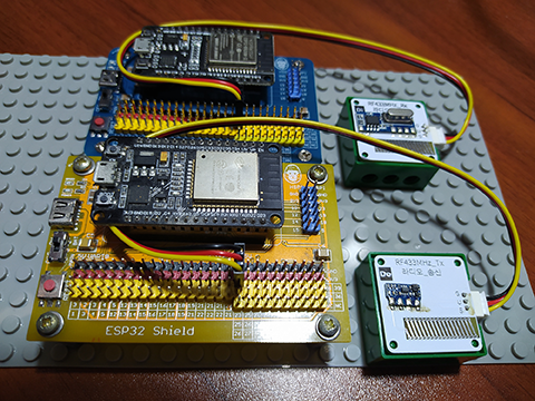
In this article, I will tackle how you can use an RF433 transceiver modules with ESP32 using MicroPython.
RF433 transmitter and receiver modules uses a radio frequency of 433 MHz which is under the Industrial, Scientific, and Medical bandwidth or ISM band for short.
PINOUTS
The RF433 transmitter and receiver module both have 3 pins which are:
- G for the ground pin
- V for the supply voltage, and
- S - for the signal pin or data pin.
- An ESP32 development board, 1 for the transmitter side and another 1 for the receiver side.
- A Gorillacell ESP32 shield, 2 pieces for both side of the circuit. This component is optional, you may use a breadboard instead if you want. Gorillacell ESP32 shield simplifies circuit connection.
- A 3-pin dupont jumper wires, 2 pieces for both side of the circuit.
- The RF433 transceivers, the receiver and the transmitter module.
- Attach the RF433 transceiver module to ESP32 as follows:
In receiver module, S pin serves as the receive data pin while in transmitter module, S pin serves as the transmitter data pin.
BILL OF MATERIALS
To follow this lesson, you will need the following:
Side-trip:
Since I don't have prior knowledge in using an RF433 transceiver modules so I did some quick research in the internet. I found this video https://www.youtube.com/watch?v=98tYLEnevfA where he demonstrates the use of the module without using any microcontroller. You might want to jump to 2:23 timestamp to just watch the demonstration.
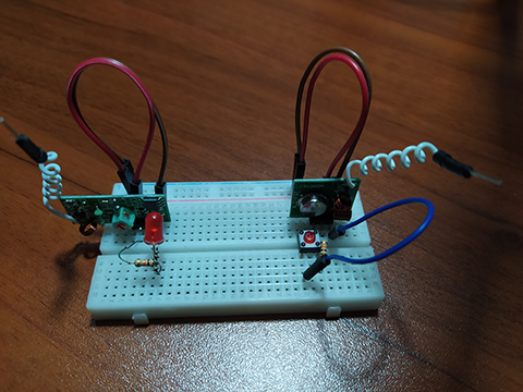
I have the exact components, so I followed the circuit but it is a bit clunky. It easily picks interference and it is not working properly.
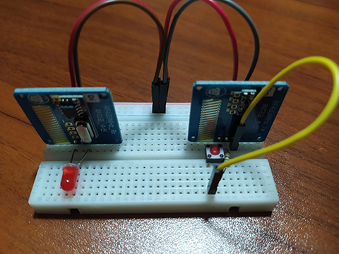
I have a spare components from Gorillacell for RF433 transceivers which produces a functional circuit.
HARDWARE INSTRUCTION:
- RF433 Rx/Tx G pin to ESP32 ground pin.
- RF433 Rx/Tx V pin to ESP32 5V pin.
- RF433 Rx/Tx S pin to ESP32 GPIO 23 pin.
SOFTWARE INSTRUCTION:
- Copy the source code and run source code to the assigned ESP32, 1 for the transmitter side and another 1 for the receiver side circuit.
- Feel free to modify the source code and please let me know if you made progress or you have any concern.
VIDEO DEMONSTRATION:
CALL TO ACTION
If you have any concern regarding this video, please write your question in the comment box.
You might also liked to support my journey on Youtube by subscribing on my channel, TechToTinker. Click this to Subscribe.
Thank you and have a good days ahead.
See you,
- George Bantique | tech.to.tinker@gmail.com
SOURCE CODE:
1. Example # 1, blinking an LED, transmitter:
# More details can be found in TechToTinker.blogspot.com
# George Bantique | tech.to.tinker@gmail.com

from machine import Pin
from time import sleep_ms

transmit = Pin(23, Pin.OUT)
sw = Pin(0, Pin.IN)

while True:
    transmit.value(not transmit.value())
    sleep_ms(50)
2. Example # 1, blinking an LED, receiver:
# More details can be found in TechToTinker.blogspot.com
# George Bantique | tech.to.tinker@gmail.com

from machine import Pin
from time import sleep_ms

receive = Pin(23, Pin.IN)
led = Pin(2, Pin.OUT)

while True:
    led.value(receive.value())
    sleep_ms(50)
3. Example # 2, sending message through RF433 modulated serial UART:
# More details can be found in TechToTinker.blogspot.com
# George Bantique | tech.to.tinker@gmail.com

from machine import Pin
from machine import UART

tx = UART(2, baudrate=9600, tx=23, rx=25)

# tx.write('This is a test messagern')
4. Example # 2, receiving message through RF433 modulated serial UART:
# More details can be found in TechToTinker.blogspot.com
# George Bantique | tech.to.tinker@gmail.com

from machine import Pin
from machine import UART

rx = UART(2, baudrate=9600, tx=25, rx=23)

# print(rx.read())
while True:
    if rx.any():
        print(rx.read())
5. Modified # 1, toggling the state of the receiver on-board LED, transmitter:
# More details can be found in TechToTinker.blogspot.com
# George Bantique | tech.to.tinker@gmail.com

from machine import Pin
from time import sleep_ms

transmit = Pin(23, Pin.OUT)
sw = Pin(0, Pin.IN)
var_sw = 1

while True:
    if sw.value()==0:       # means, sw is pressed!
        var_sw = not var_sw # toggle the state of variable
    transmit.value(var_sw)  # send it to the radio
    sleep_ms(50)
6. Modified # 1, toggling the state of the receiver on-board LED, transmitter:
REFERENCES AND CREDITS:
1. Purchase your Gorillacell ESP32 development kits:
2. Video showing the use of RF433 transceiver modules without an MCU:
