How to Get Started with L298N Motor Driver module using Arduino
Table of Contents
The L298N motor driver module is a cheap solution when you need to drive 2 DC motors or 1 stepper motor. It is a popular motor driver module among DIYers and hobbyists due to its ease of use and availability.
Features:
It has a dual H-bridge motor driver.
Onboard 5V linear voltage regulator means you can supply the voltage requirements of other circuits.
Below are the pin assignments and their configurations.
Power Terminal Block:
+12V:
- Positive motor supply voltage
- If the motor supply voltage is more than 12V, make sure the jumper pin in CON5 is removed. This protects the onboard 5V linear voltage regulator from damage.
GND:
- Common ground for the L298N and the interface microcontroller
+5V:
- Input voltage supply for the L298N IC when the onboard 5V linear voltage regulator is disabled (jumper pin in CON5 is removed).
- Output voltage supply for the interface microcontroller when the linear voltage regulator is enabled (jumper pin in CON5 is in place).
Bidirectional Motor Driver Output:
MotorA: motor driver output for MotorA
MotorB: motor driver output for MotorB
Enable and Speed Controller:
enA: enable pin A
- Pull down (connect to GND) to disable motor driver output for MotorA
- Pull up (connect to VCC) to enable motor driver output for MotorB (similar results can be achieved using a jumper pin)
- PWM to control speed of the motor
enB: enable pin B
- Pull down (connect to GND) to disable motor driver output for MotorA
- Pull up (connect to VCC) to enable motor driver output for MotorB (similar results can be achieved using a jumper pin)
- PWM to control speed of the motor
Direction Logic Controller:
IN1 and IN2:
- Direction logic controller for MotorA
IN3 and IN4:
- Direction logic controller for MotorB
PWR jumper pin:
- Enables the onboard voltage regulator
CIRCUIT DIAGRAM
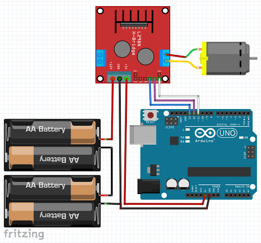
- Referring to the circuit diagram, I am supplying the L298N with 6V battery. +6V is connected to the +12V pin motor supply voltage.
- Battery GND pin is connected to the GND pin of the L298N.
- Arduino GND is also tied to the L298N GND pin, this is to create a common reference ground.
- 5V pin of Arduino is tied to the L298N +5V pin to supply voltage for the L298N IC. Please notice also that the jumper pin in the CON5 is removed to disable the onboard 5V voltage regulator of the L298N.
- DC motor is connected to the terminal block MotorB in the right side.
- IN3 and IN4 is tied to Arduino Uno digital pin 13 and 12 to control the direction of motor rotation.
- EnB is tied to Arduino Uno digital pin 11. This pin has a capability of outputting a Pulse Width Modulation (PWM) signal. This is to control the speed of rotation of the motor.
VIDEO DEMONSTRATION
SOURCE CODE
#define IN3B 13
#define IN4B 12
#define PWMB 11

String cmd="";
bool isBEnabled = false;
byte PWMB_val = 100;

void setup() {
  // put your setup code here, to run once:
  Serial.begin(9600);

  pinMode(IN3B, OUTPUT);
  pinMode(IN4B, OUTPUT);
  pinMode(PWMB, OUTPUT);

  digitalWrite(IN3B, LOW);
  digitalWrite(IN4B, LOW);
  digitalWrite(PWMB, LOW);
}

void loop() {
  // put your main code here, to run repeatedly:
  checkSerial();
}


void checkSerial() {
 //Read data from Serial
 while(Serial.available()>0){
   cmd+=(char)Serial.read();
 }

 //Select function with cmd
 if(cmd!=""){
    cmd.trim();  // Remove added LF in transmit
    // We expect Command from bluetooth
    if (cmd.equals("E")) {
      Serial.println("Enabling motor");
      enableB();
    } else if(cmd.equals("R")) {
       Serial.println("CW Rotation");
       forward();
    }else if (cmd.equals("L")){
       Serial.println("CCW Rotation");
       backward();
    }else if(cmd.equals("U")){
       Serial.println("Speed up");
       speedUp();
    }else if(cmd.equals("D")){
       Serial.println("Speed down");
       speedDown();
    }
    cmd=""; //reset cmd
  }

void enableB() {
  if (isBEnabled) {
    // motor is running, now disable it
    isBEnabled = false;
    digitalWrite(PWMB, 0);
  } else {
    // motor is disabled, now run it
    isBEnabled = true;
    analogWrite(PWMB, PWMB_val);
  }
}

void forward() {
  digitalWrite(IN3B, LOW);
  digitalWrite(IN4B, HIGH);
}

void backward() {
  digitalWrite(IN3B, HIGH);
  digitalWrite(IN4B, LOW);
}

void speedUp() {
  if (PWMB_val < 245) {
    PWMB_val = PWMB_val + 10;
    analogWrite(PWMB, PWMB_val);
  }
}

void speedDown () {
  if (PWMB_val > 9) {
    PWMB_val = PWMB_val - 10;
    analogWrite(PWMB, PWMB_val);
  }
}
CALL TO ACTION
That's all for now. If you have any questions or clarification, please feel free to leave your comments and suggestions in the comments
Thank you and have a good day.
Happy tinkering.