026 - MicroPython TechNotes: Light Dependent Resistor (LDR)
Table of Contents
In this article, we will learn how to use an LDR with ESP32 using MicroPython programming language. LDR stands for Light Dependent Resistor. It is a type of electronic component that changes resistance according to the light intensity.
PINOUT
- G – for the ground.
- V – for the supply voltage.
- S – for the signal pin.
BILL OF MATERIALS
- An ESP32 development board to serve as the brain for the experiment.
- Gorillacell ESP32 shield to extend ESP32 pins to pin headers for easy circuit connection.
- A 3-pin female-female dupont jumper wires to attach the LDR module to the ESP32 shield.
- An LDR sensor module itself.
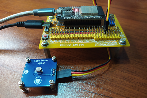
HARDWARE INSTRUCTION
- First, attach the ESP32 board on top of the ESP32 shield and make sure that both USB port are on the same side.
- Next, attach the dupont jumper wires to the LDR module by following a color coding which is black for the ground, red for the VCC, and yellow for the signal pin.
- Next, attach the other end of the dupont wires to the ESP32 shield by matching the colors of the wires to the colors of the pin headers such as black to black, red to red, and yellow to yellow. For this, I choose GPIO 32 to serve as analog input pin from the LDR module.
- Next, power the ESP32 shield with an external power supply with a type-C USB cable and make sure that the power switch is set to the ON state.
- Lastly, connect the ESP32 to the computer using a micro-USB cable.
SOFTWARE INSTRUCTION
For this experiment, I prepared 3 examples.
Copy and paste it to your Thonny IDE.
Please feel free to modify it according to your needs.
Happy tinkering.
VIDEO DEMONSTRATION
CALL TO ACTION
For any concern, write your message in the comment section.
You might also like to support my journey on Youtube by Subscribing. Click this to Subscribe to TechToTinker.
Thank you and have a good days ahead.
See you,
– George Bantique | tech.to.tinker@gmail.com
SOURCE CODE
1. Example # 1, basics of reading an LDR module
# More details can be found in TechToTinker.blogspot.com
# George Bantique | tech.to.tinker@gmail.com

from machine import Pin, ADC

LDR = ADC(Pin(32, Pin.IN))
LDR.atten(ADC.ATTN_11DB)

# The following line of codes can be tested using the REPL:
#print(LDR.read())
2. Example # 2, automatic lights using an LDR
# More details can be found in TechToTinker.blogspot.com
# George Bantique | tech.to.tinker@gmail.com

from machine import Pin, ADC
from time import sleep_ms

LDR = ADC(Pin(32, Pin.IN))
LDR.atten(ADC.ATTN_11DB)
led = Pin(2, Pin.OUT)

while True:
   ldr_value = LDR.read()
   if ldr_value < 2400:
     # Its dark
     led.on()
   elif ldr_value > 2500:
     # Its bright
     led.off()
   sleep_ms(50)
How the code works
from machine import Pin, ADCImports the Pin class and the ADC class from the machine module. Pin class is used to access ESP32 pins while ADC class is used to read the LDR sensor module.
LDR = ADC(Pin(32, Pin.IN))
LDR.atten(ADC.ATTN_11DB)
Creates the ADC object named LDR which is connected on GPIO 32 with a pin direction of input.
# The following line of codes can be tested using the REPL:
print(LDR.read())
Prints the current LDR value by reading the ADC value of the LDR pin in the REPL.
from machine import Pin, ADCImports the Pin class and the ADC class from the machine module. Pin class is use in order to access ESP32 pins while ADC class is use to read the LDR sensor module.
from time import sleep_msImports the sleep_ms class from the time module. Sleep_ms is in milliseconds resolution.
LDR = ADC(Pin(32, Pin.IN))
LDR.atten(ADC.ATTN_11DB)
Creates the ADC object named LDR which is connected on GPIO 32 with a pin direction of input.
led = Pin(2, Pin.OUT)Creates a pin class named led which is connected to GPIO 2 (on board LED) with a pin direction set as output.
while True:Creates an infinite loop.
ldr_value = LDR.read()Reads the LDR value by reading it through an ADC and stores it to ldr_value variable.
if ldr_value < 2400:
    # Its dark
    led.on()
elif ldr_value > 2500:
    # Its bright
    led.off()
Checks if the LDR value signifies dark, then turn ON the LED else if its bright, turn OFF the LED.
sleep_ms(50)Creates a 50 milliseconds interval in between the LDR readings.
3. Example # 3, Intruder Detection Security System
# More details can be found in TechToTinker.blogspot.com
# George Bantique | tech.to.tinker@gmail.com

from machine import Pin, ADC
from time import sleep_ms

LDR = ADC(Pin(32, Pin.IN))
LDR.atten(ADC.ATTN_11DB)

laser = Pin(25, Pin.OUT)
laser.on()

led = Pin(2, Pin.OUT)

isAlert = False
print(LDR.read())

while True:
    if LDR.read() < 3000:
        isAlert = True
    else:
        isAlert = False

    if isAlert:
        led.value(not led.value())
        sleep_ms(100)
How the code works
from machine import Pin, ADCImports the Pin class and the ADC class from the machine module. Pin class is use in order to access ESP32 pins while ADC class is use to read the LDR sensor module.
from time import sleep_msImports the sleep_ms class from the time module. Sleep_ms is in milliseconds resolution.
LDR = ADC(Pin(32, Pin.IN))
LDR.atten(ADC.ATTN_11DB)
Creates the ADC object named LDR which is connected on GPIO 32 with a pin direction of input.
led = Pin(2, Pin.OUT)Creates a pin class named led which is connected to GPIO 2 (on board LED) with a pin direction set as output.
isAlert = FalseInitialize the isAlert variable to False (means no intruder currently detected)
while True:Creates an infinite loop.
if LDR.read() < 3000:
    isAlert = True
else:
    isAlert = False
Checks if LDR value is below the threshold (if the laser light is obstructed), if yes, set the isAlert variable to True (which means that the laser light is obstructed or cut, an intruder is detected) else set the isAlert variable to False.
if isAlert:
    led.value(not led.value())
    sleep_ms(100)
If an intruder is detected, blinks the onboard LED every 100 milliseconds. You can also add audible alarm or send an alert message to the owner of the establishment.
REFERENCES AND CREDITS
1. Purchase your Gorillacell ESP32 development kit at: